Cisco virtual Port Channel (vPC) is a virtualization technology, launched in 2009, which allows links that are physically connected to two different Cisco Nexus Series devices to appear as a single port channel to a third endpoint. The endpoint can be a switch, server, router or any other device such as Firewall or Load Balancers that support the link aggregation technology (EtherChannel).
To correctly design and configure vPC one must have sound knowledge of the vPC architecture components (vPC Domain, vPC Peer, vPC Peer-Link, vPC Peer Keepalive Link, vPC Member Port, vPC Orphan Port etc) but also follow the recommended design guidelines for the vPC Peer Keepalive Link and vPC Peer-Link. Furthermore, understanding vPC failure scenarios such as vPC Peer-Link failure, vPC Peer Keepalive Link failure, vPC Peer Switch failure, vPC Dual Active or Split Brain failure will help plan ahead to minimise network service disruption in the event of a link or device failure.
All the above including verifying & troubleshooting vPC operation are covered extensively in this article making it the most comprehensive and complete Cisco Nexus vPC guide.
The diagram below clearly illustrates the differences in both logical and physical topology between a non-vPC deployment and a vPC deployment:

vPC Deployment Concept
The Cisco Nexus vPC technology has been widely deployed and in particular by almost 95% of Cisco Data Centers based on information provided by the Cisco Live Berlin 2016. In addition, virtual Port Channel was introduced in NX-OS version 4.1(4) and is included in the base NX-OS software license. This technology is supported on the Nexus 9000, 7000, 5000 and 3000 Series.
Let's take a look at the vPC topics covered:
We must point out that basic knowledge of the Cisco NX-OS is recommended for this article. You can also refer to our Introduction to Nexus Family – Nexus OS vs Catalyst IOS for an introduction study on the Nexus Series switches family. Finally, a Quiz is included at the last section and we are waiting for your comments and answers!
Additional related articles:
The Nexus 9000, 7000, 5000 and 3000 series switches take port-channel functionality to the next level by enabling links connected to different devices to aggregate into a single, logical link. The peer switches run a control protocol that synchronizes the state of the port channel and maintains it. In particular, the vPC belongs to the Multichassis EtherChannel (MEC) family of technology and provides the following main technical benefits:
- Eliminates Spanning Tree Protocol (STP) blocked ports
- Uses all available uplink bandwidth
- Allows dual-homed servers (dual uplinks) to operate in active-active mode
- Provides fast convergence upon link or device failure
- Offers dual active/active default gateways for servers
- Maintains independent control planes
- Simplifies Network Design
The following general guidelines and recommendations should be taken into account when deploying vPC technology at a Cisco Nexus Data Center:
- The same type of Cisco Nexus switches must be used for vPC pairing. It is not possible to configure vPC on a pair of switches consisting of a Nexus 7000 series and a Nexus 5000 series switch. vPC is not possible between a Nexus 5000 and Nexus 5500 switches.
- The vPC peers must run the same NX-OS version except during the non-disruptive upgrade, that is, In-Service Software Upgrade (ISSU).
- The vPC Peer-Link must consist of at least two 10G Ethernet ports in dedicated mode. Utilizing Ethernet ports from two different modules will improve the availability and redundancy should a module fail. Finally the use of 40G or 100G interfaces for vPC links will increase the bandwidth of the vPC Peer-Link.
- vPC keepalive link must be separate from the vPC Peer-Link.
- vPC can be configured in multiple VDCs, but the configuration is entirely independent. In particular, each VDC for the Nexus 7000 Series switches requires its own vPC peer and keepalive links and cannot be shared among the VDCs.
- The maximum number of switches in a vPC domain is two.
- The maximum number of vPC peers per switch or VDC is one.
- When Static routing from a device to vPC peer switches with next hop, FHRP virtual IP is supported.
- Dynamic routing adjacency from vPC peer switches to any Layer3 device connected on a vPC is not supported. It is recommended that routing adjacencies are established on separate routed links.
- vPC member ports must be on the same line card type e.g. M2 type cards at each end.
vPC architecture consists of the following components:
vPC Peer
This is the adjacent device, which is connected via the vPC Peer-link. A vPC setup consists of two Nexus devices in a pair. One acts as the Primary and the other as a Secondary, which allows other devices to connect to the two chassis using Multi-Channel Ethernet (MEC).

vPC Architecture Components
vPC Peer-link
The vPC peer-link is the most important connectivity element in the vPC setup. This link is used to synchronize the state between vPC peer devices via vPC control packets which creates the illusion of a single control plane. In addition the vPC peer-link provides the necessary transport for multicast, broadcast, unknown unicast traffic and for the traffic of orphaned ports. Finally, in the case of a vPC device that is also a Layer 3 switch, the peer-link carries Hot Standby Router Protocol (HSRP) packets.
vPC Peer Keepalive Link
The Peer Keepalive Link provides a Layer 3 communications path that is used as a secondary test in order to determine whether the remote peer is operating properly. In particular, it helps the vPC switch to determine whether the peer link itself has failed or whether the vPC peer is down. No data or synchronization traffic is sent over the vPC Peer Keepalive Link—only IP/UDP packets on port 3200 to indicate that the originating switch is operating and running vPC. The default timers are an interval of 1 second with a timeout of 5 seconds.
vPC Domain
This is the common domain configured across two vPC peer devices and this value identifies the vPC. A vPC domain id per device is permitted.
vPC Member Port
This is the interface that is a member of one of the vPCs configured on the vPC peers.
Cisco Fabric Services (CFS)
This protocol is used for stateful synchronization and configuration. It utilizes the peer link and does not require any configuration by the administrators. The Cisco Fabric Services over Ethernet protocol is used to perform compatibility checks in order to validate the compatibility of vPC member ports to form the channel, to synchronize the IGMP snooping status, to monitor the status of the vPC member ports, and to synchronize the Address Resolution Protocol (ARP) table.
Orphan Device
This is a device that is on a VPC VLAN but only connected to one VPC peer and not to both.
Orphan Port
An orphan port is an interface that connects to an orphan device vPC VLAN.
non-vPC VLAN
Any of the STP VLANs not carried over the peer-link.
Virtual Switching System (VSS) is a virtualization technology that pools multiple Cisco Catalyst Switches into one virtual switch, increasing operational efficiency, boosting nonstop communications, and scaling system bandwidth capacity. VSS was first available in the Cisco 6500 series and was later introduced to the Cisco 4500, the newer 4500X, 6800 Series switches and the Catalyst 3850 (April 2017 onwards).
The vPC feature is currently not supported by any Cisco Catalyst Series Switches and is available only on the Nexus switches family.
While VSS makes use of Multi Ether Channel (MEC) to bond Cisco Catalyst Series switches together, vPC is used on Cisco Nexus Series switches for the same purpose. Both technologies are similar from the perspective of the downstream switch but there are differences, mainly in that the control plane works on the upstream devices. The next table summarizes the main characteristics and features of the VSS and vPC technologies:
|
Feature
|
VSS
|
vPC
|
|
Multi-Chassis Port Channel
|
Yes
|
Yes
|
|
Loop Free Topology
|
Yes
|
Yes
|
|
Spanning Tree as failsafe protocol
|
Yes
|
Yes
|
|
Maximum physical Nodes
|
2
|
2
|
|
No Disruptive ISSU support
|
No
|
Yes
|
|
Control Plane
|
Single logical node
|
Two independents active nodes
|
|
Layer 3 port channel
|
YES
|
Limited
|
|
Configuration
|
Common configuration
|
Two different configurations
|
|
Etherchannel
|
Static, PAgP, PAgP, LACP
|
Static, LACP
|
Table 1. Comparing Catalyst VSS with Nexus vPC
Deploying MEC or vPC could require minimal changes to an existing switching infrastructure. Catalyst Switches may need a supervisor engine upgrade to form a VSS. Then, the primary loop avoidance mechanism is provided by MEC or vPC control protocols. STP is still in operation but is running only as a failsafe mechanism. Finally, the devices e.g. access switches, servers, etc., should be connected with multiple links to Data Center Distribution or Core switches. Link Aggregation Control Protocol (LACP) is the protocol that allows for dynamic portchannel negotiation and allows up to 16 physical interfaces to become members of a single port channel.
Taking into account the importance and impact of the Peer Keepalive link and vPC Peer-Link, Cisco recommends the following type of interconnections for the vPC Keepalive link:
|
Recommendations in order of preference for the vPC Keepalive link interconnection
|
|
Nexus 7000 & 9000 Series Switches
|
Nexus 5000 & 3000 Series Switches
|
|
1. Dedicated link(s) (1GE LC)
|
1. mgmt0 interface (along with management traffic) |
|
2. mgmt0 interface (along with management traffic)
|
2. Dedicated link(s) (1/10GE front panel ports) |
|
3. As last resort, can be routed in-band over the L3 infrastructure
|
Table 2. vPC Keepalive Link Interconnection methods
Special attention is needed where the mgmt interfaces of a Nexus are used to route the vPC keepalive packets via an Out of Band (OOB) Management switch. Turning off the OOB Management switch, or removing by accident the keepalive links from this switch in parallel with vPC Peer-Link failure, could lead to split brain scenario and network outage.
Using a dedicated interface for vPC keepalive link has the advantage that there’s no other network device that could affect the vPC keepalive link. Using point to point links makes it easier to control the path and minimizes the risk of failure. However, an interface for each vPC peer switch should be used to host the keepalive link. This could be a problem where there’s a limited number of available interfaces or SFPs.
Layer 3 connectivity for the Keepalive Link can be accomplished either with the SVI or with L3 (no switchport) configuration of the interfaces involved. The SVI configuration is the only option where the Nexus vPC Peer switches do not support L3 features. In any case, it is recommended to set the Keepalive Link to a separate VRF in order to isolate it from the default VRF. If the SVI is configured to route the keepalive packets, then this vlan should not be routed over vPC link. This is why the Keepalive VLAN should be removed from the trunk allowed list of the vPC Peer-Link or the vPC member ports. Allowing the Keepalive VLAN over the vPC peer trunk could lead to split brain scenario (analyzed below) and network outage if the vPC Peer-Link fails!
The following design guidelines are recommended for the vPC Peer-Links:
- Member ports must be at least 10GE interfaces.
- Use only point-to-point without other devices between the vPC peers (Nexus switches). E.g. transceivers, microwave bridge link, etc.
- Use at least two 10Gbps links spread between two separate I/O module cards at each switch for best resiliency.
- The ports should be in dedicated mode for the oversubscribed modules.
- vPC Peer-Link ports should be located on a different I/O module than that used by the Peer Keepalive Link.
The next section describes how the vPC Nexus switches interact with events triggered by failure of links (vPC Peer Keepalive Link, Peer-Link etc) or vPC Peer switch.
In the scenario the vPC Peer-Links on the Secondary Nexus fail the status of the peer vPC is examined using the Peer Keepalive Link:

vPC Peer-Link Failure Scenario
If both vPC peers are active, the secondary vPC (i.e. the switch with the higher priority) disables all the vPC member ports to avoid uncertain traffic behavior and network loops which can result in service disruption.
At this point traffic continues flowing through the Primary vPC without any disruptions.
In the unfortunate event there is an orphan device connected to the secondary peer, then its traffic will be black-holed.
In the event the Peer Keepalive Link fails it will not have a negative effect on the operation of the vPC, which will continue forwarding traffic. The Keepalive Link is used as a secondary test mechanism to confirm the vPC peer is live in case the Peer-Link goes down:

vPC Peer Keepalive Link Failure Scenario
During a Keepalive Link failure there is no change of roles between the vPC (primary/secondary) and no down time in the network.
As soon as the Keepalive Link is restored the vPC will continue to operate.
In the case of a vPC peer switch total failure, the remote switch learns from the failure via the Peer Keepalive link since no keepalive messages are received. The data traffic is forwarded by utilizing the remaining links til the failed switch recovers. It should be noticed that the Keepalive messages are used only when all the links in the Peer-Link fail:

vPC Peer Switch Failure Scenario
Spanning Tree Protocol is used as a loop prevention mechanism in the case of a Peer Keepalive Link and vPC Peer-Link simultaneous failure.
The Dual-Active or Split Brain vPC failure scenario occurs when the Peer Keepalive Link fails followed by the Peer-Link. Under this condition both switches undertake the vPC primary roles.
If this happens, the vPC primary switch will remain as the primary and the vPC secondary switch will become operational primary causing severe network instability and outage:

vPC Dual-Active or Split Brain Failure Scenario
The vPC is configured and normal operation is verified by following the nine steps defined below. It should be noted that the order of the vPC configuration is important and that a basic vPC setup is established by using the first 4 steps:

vPC Configuration Steps
Step 1: Enable the vPC feature and configure the vPC domain ID on both Nexus switches.
Step 2: Select a Peer Keepalive deployment option.
Step 3: Establish the vPC peer keepalive link.
Step 4: Configure the vPC Peer-Link.
Step 4 completes the global vPC configuration on both vPC peer switches.
Step 5: Configure individual vPCs to downstream switches or devices.
Step 6: Optionally, enable the peer gateway feature to modify the First Hop Redundancy Protocol (FHRP) operation.
Step 7: Optionally, enable the peer switch feature to optimize the STP behaviour with vPCs.
Step 8: Optionally, enable the additional features to optimize the vPCs setup.
Step 9: Optionally, verify operation of the vPC and vPC consistency parameters.
To help illustrate the setup of the vPC technology we used two Nexus 5548 data center switches. Typically, a similar process would be followed for any other type of Nexus switches.
Our two Nexus 5548 were given hostnames N5k-Primary & N5k-Secondary and the order outlined above was followed for the vPC setup and configuration:
Step 1: Enable the vPC Feature and Configure the vPC Domain ID on Both Switches
Following are the commands used to enable vPC and configure the vPC domain ID on the first switch:
N5k-Primary(config)# feature vpc
N5k-Primary(config)# vpc domain 1
N5k-Primary(config-vpc-domain)# show vpc role
vPC Role status
----------------------------------------------------
vPC role : none established
Dual Active Detection Status : 0
vPC system-mac : 00:23:04:ee:be:01
vPC system-priority : 32667
vPC local system-mac : 8c:60:4f:2c:b3:01
vPC local role-priority : 0
Now we configure the Nexus Secondary switch using the same commands:
N5k-Secondary(config)# feature vpc
N5k-Secondary(config)# vpc domain 1
N5k-Secondary(config-vpc-domain)# show vpc role
vPC Role status
----------------------------------------------------
vPC role : none established
Dual Active Detection Status : 0
vPC system-mac : 00:23:04:ee:be:01
vPC system-priority : 32667
vPC local system-mac : 8c:60:4f:aa:c2:3c
vPC local role-priority : 0
The same domain ID (ID 1 in our example) must be used on both vPC peer switches in the vPC domain. The output of the show vpc role command shows that the system MAC address is derived from the vPC domain ID, which is equal to 01.
Step 2: Choose a Peer Keepalive Deployment Option
Our setup below utilizes the SVI technology and the second option (dedicated 1G link) proposed for the N5k series switches keepalive link setup (table 2). This deployment option involves a dedicated VLAN with a configured SVI used for the keepalive link within an isolated VRF (named keepalive) for complete isolation from the rest of the network. Interface Ethernet 1/32 is used by both switches as a dedicated interface for the keepalive link.
On the first switch we create VLAN 23 with an SVI (assign an IP address to the VLAN interface) and make it a member of the VRF instance created for this purpose. We complete the configuration by assigning Ethernet 1/32 to VLAN 23:
N5k-Primary(config)# vlan 23
N5k-Primary(config-vlan)# name keepalive
N5k-Primary(config)# vrf context keepalive
interface Vlan23
vrf member keepalive
ip address 192.168.1.1/24
interface Ethernet1/32
switchport access vlan 23
speed 1000
duplex full
We follow the same configuration steps on our Secondary Nexus switch:
N5k-Secondary (config)# vlan 23
N5k-Secondary(config-vlan)# name keepalive
N5k-Secondary(config)# vrf context keepalive
interface Vlan23
vrf member keepalive
ip address 192.168.1.2/24
interface Ethernet1/32
switchport access vlan 23
speed 1000
duplex full
The ping connectivity test between the Peer Keepalive Links is successful:
N5k-Secondary# ping 192.168.1.1 vrf keepalive
PING 192.168.1.1 (192.168.1.1): 56 data bytes
36 bytes from 192.168.1.2: Destination Host Unreachable
Request 0 timed out
64 bytes from 192.168.1.1: icmp_seq=1 ttl=254 time=3.91 ms
64 bytes from 192.168.1.1: icmp_seq=2 ttl=254 time=3.05 ms
64 bytes from 192.168.1.1: icmp_seq=3 ttl=254 time=1.523 ms
64 bytes from 192.168.1.1: icmp_seq=4 ttl=254 time=1.501 ms
Note: The initial ICMP timeout is normal behavior as the switch needs to initially send out an ARP request to obtain 192.168.1.1’s MAC address and then send the ICMP (ping) packet.
Step 3: Establish the vPC Peer Keepalive Link
By default, the vPC Peer Keepalive packets are routed in the management VRF and use the Out-Of-Band (OOB) mgmt interface.
It is, however, highly recommended to configure the vPC Peer Keepalive link to use a separate VRF instance to ensure that the peer keepalive traffic is always carried on that link and never on the Peer-Link. In addition, the keepalive vlan should be removed from the trunk allowed list of the vPC Peer-Link or the vPC Member Ports.
N5k-Primary(config)# vpc domain 1
N5k-Primary (config-vpc-domain)# peer-keepalive destination 192.168.1.2 source 192.168.1.1 vrf keepalive
Configuration of the Secondary vPC follows:
N5k-Secondary(config)# vpc domain 1
N5k-Secondary(config-vpc-domain)# peer-keepalive destination 192.168.1.1 source 192.168.1.2 vrf keepalive
We can verify the status of the vPC Peer Keepalive Link using the show vpc peer-keepalive command on both switches:
N5k-Primary# show vpc peer-keepalive
vPC keep-alive status : peer is alive
--Peer is alive for : (95) seconds, (201) msec
--Send status : Success
--Last send at : 2017.06.22 23:03:50 720 ms
--Sent on interface : Vlan23
--Receive status : Success
--Last receive at : 2017.06.22 23:03:50 828 ms
--Received on interface : Vlan23
--Last update from peer : (0) seconds, (201) msec
vPC Keep-alive parameters
--Destination : 192.168.1.2
--Keepalive interval : 1000 msec
--Keepalive timeout : 5 seconds
--Keepalive hold timeout : 3 seconds
--Keepalive vrf : keepalive
--Keepalive udp port : 3200
--Keepalive tos : 192
Verifying the status of the vPC Peer Keepalive Link on our Secondary switch:
N5k-Secondary# show vpc peer-keepalive
vPC keep-alive status : peer is alive
--Peer is alive for : (106) seconds, (385) msec
--Send status : Success
--Last send at : 2017.06.22 22:46:32 106 ms
--Sent on interface : Vlan23
--Receive status : Success
--Last receive at : 2017.06.22 22:46:32 5 ms
--Received on interface : Vlan23
--Last update from peer : (0) seconds, (333) msec
vPC Keep-alive parameters
--Destination : 192.168.1.1
--Keepalive interval : 1000 msec
--Keepalive timeout : 5 seconds
--Keepalive hold timeout : 3 seconds
--Keepalive vrf : keepalive
--Keepalive udp port : 3200
--Keepalive tos : 192
Step 4: Configure the vPC Peer-Link
This step completes the global vPC configuration on both vPC peer switches and involves the creation of the Port-Channel to be used as the vPC Peer-Link.
First we need to enable the lacp feature then create our high-capacity port channel between the two switches to carry all necessary traffic.
The interfaces Eth1/2 and Eth1/3 are selected to become members of the vPC Peer-Link in LACP mode. In addition, the vPC is configured as a trunk. The allowed VLAN list for the trunk should be configured in such a way that only vPC VLANs (VLANs that are present on any vPCs) are allowed on the trunk. VLAN 10 has been created and allowed on the vPC Peer-Link:
N5k-Primary (config)# feature lacp
N5k-Primary(config)# interface ethernet 1/2-3
N5k-Primary(config-if-range)# description *** VPC PEER LINKS ***
N5k-Primary(config-if-range)# channel-group 23 mode active
N5k-Primary(config)# vlan 10
N5k-Primary(config)# interface port-channel 23
N5k-Primary(config-if)# description *** VPC PEER LINKS ***
N5k-Primary(config-if)# switchport mode trunk
N5k-Primary(config-if)# switchport trunk allowed vlan 10
N5k-Primary(config-if)# vpc peer-link
Please note that spanning tree port type is changed to "network" port type on vPC peer-link. This will enable spanning tree Bridge Assurance on vPC peer-link provided the STP Bridge Assurance(which is enabled by default) is not disabled.
N5k-Primary(config-if)# spanning-tree port type network
An identical configuration follows for our Secondary switch:
N5k-Secondary(config)# feature lacp
N5k-Seondary(config)# interface ethernet 1/2-3
N5k-Secondary(config-if-range)# description *** VPC PEER LINKS ***
N5k-Secondary(config-if-range)# channel-group 23 mode active
N5k-Seondary(config)# vlan 10
N5k-Secondary(config)# interface port-channel 23
N5k-Secondary(config-if)# description *** VPC PEER LINKS ***
N5k-Secondary(config-if)# switchport mode trunk
N5k-Secondary(config-if)# switchport trunk allowed vlan 10
N5k-Secondary(config-if)# vpc peer-link
Please note that spanning tree port type is changed to "network" port type on vPC peer-link. This will enable spanning tree Bridge Assurance on vPC peer-link provided the STP Bridge Assurance (which is enabled by default) is not disabled
N5k-Secondary(config-if)# spanning-tree port type network
It is not recommended to carry non-vPC VLANs on the vPC Peer-Link, because this configuration could cause severe traffic disruption for the non-vPC VLANs if the vPC Peer-Link fails. Finally, the vPC Peer Keepalive messages should not be routed over the vPC Peer-Link, which is why the VLAN associated with the Peer Keepalive connection (VLAN 23) is not allowed on the vPC Peer-Link.
We can perform a final check on our vPC using the show vpc command:
N5k-Primary# show vpc
Legend:
(*) - local vPC is down, forwarding via vPC peer-link
vPC domain id : 1
Peer status : peer adjacency formed ok
vPC keep-alive status : peer is alive
Configuration consistency status : success
Per-vlan consistency status : success
Type-2 consistency status : success
vPC role : primary
Number of vPCs configured : 0
Peer Gateway : Disabled
Dual-active excluded VLANs : -
Graceful Consistency Check : Enabled
Auto-recovery status : Enabled (timeout = 240 seconds)
vPC Peer-link status
---------------------------------------------------------------------
id Port Status Active vlans
-- ---- ------ --------------------------------------------------
1 Po23 up 10
Verifying the vPC on the Secondary peer:
N5k-Secondary# show vpc
Legend:
(*) - local vPC is down, forwarding via vPC peer-link
vPC domain id : 1
Peer status : peer adjacency formed ok
vPC keep-alive status : peer is alive
Configuration consistency status : success
Per-vlan consistency status : success
Type-2 consistency status : success
vPC role : secondary, operational primary
Number of vPCs configured : 0
Peer Gateway : Disabled
Dual-active excluded VLANs : -
Graceful Consistency Check : Enabled
Auto-recovery status : Enabled (timeout = 240 seconds)
vPC Peer-link status
---------------------------------------------------------------------
id Port Status Active vlans
-- ---- ------ --------------------------------------------------
1 Po23 up 10
The show vpc output shows that the vPC Peer-Link has been successfully established between the Nexus 5548 switches.
Step 5: Configure Individual vPCs to Downstream Devices
Individual vPCs can now be configured since the vPC domain has been properly established in the previous step.
Individual vPCs are used to connect network devices to both data center switches. For example, a router or server can connect with two or more network interfaces to both switches simultaneously for increased redundancy and bandwidth availability.
For each individual vPC, a port channel is configured on both vPC peer switches. The two port channels are then associated with each other by assigning a vPC number to the port channel interfaces:
interface Ethernet1/1
description *** Connected to ISR Gig0/2/4 ***
switchport access vlan 10
speed 1000
channel-group 10
interface port-channel10
switchport access vlan 10
vpc 10
In our setup, vpc index 10 has been assigned to port-channel 10. It is generally good practice to keep the port-channel (e.g. port-channel 10) and vpc index (e.g. vpc 10) the same to make tracking easier and avoid configuration mistakes.
Finally the vPC port number (e.g. port-channel 10) to the downstream device (e.g router) is unique for each individual vPC within the vPC domain and must be identical between the two peer switches as shown in the diagram below:

Nexus vPC port-channel configuration to downstream devices
Finally the vPC member ports should have a compatible and consistent configuration for all the ports to both switches. Here is the configuration on the Primary Nexus switch:
interface Ethernet1/1
description *** Connected to ISR Gig0/2/0 ***
switchport access vlan 10
speed 1000
channel-group 10
interface port-channel10
switchport access vlan 10
vpc 10
Verifiying our vPC to the downstream device from the Primary vPC:
N5k-Primary# show vpc | begin "vPC status"
vPC status
----------------------------------------------------------------------------
id Port Status Consistency Reason Active vlans
------ ----------- ------ ----------- -------------------------- -----------
10 Po10 up success success 10
Verifiying our vPC to the downstream device from the Secondary vPC:
N5k-Secondary# show vpc | begin "vPC status"
vPC status
----------------------------------------------------------------------------
id Port Status Consistency Reason Active vlans
------ ----------- ------ ----------- -------------------------- -----------
10 Po10 up success success 10
Step 6: (Optional) Enable the Peer-Gateway Feature to Modify the FHRP Operation
The vPC Peer-Gateway feature causes a vPC peer to act as a gateway for packets that are destined for the peer device’s MAC address. So, it enables local forwarding of such packets without the need to cross the vPC Peer-Link. This feature optimizes the use of the peer link and avoids potential traffic loss in FHRP scenarios.
When enabled, the peer gateway feature must be configured on both primary and secondary vPC peers:
N5k-Primary(config)# vpc domain 1
N5k-Primary(config-vpc-domain)# peer-gateway
Configuring the secondary vPC peer:
N5k-Secondary(config)# vpc domain 1
N5k-Secondary(config-vpc-domain)# peer-gateway
Step 7: (Optional) Enable the Peer-Switch Feature to Optimize the STP Behaviour with the vPCs
This feature allows a pair of Cisco Nexus switches to appear as a single spanning tree root in the Layer 2 topology. It eliminates the need to pin the spanning tree root to the vPC primary switch and improves vPC convergence if the vPC primary switch fails:
N5k-Primary(config)# vpc domain 1
N5k-Primary(config-vpc-domain)# peer-switch
Configuring the peer-switch command on the Secondary vPC:
N5k-Secondary(config)# vpc domain 1
N5k-Secondary(config-vpc-domain)# peer-switch
Step 8: (Optional) Optimize vPC performance: ‘ip arp synchronize’, ‘delay restore’, ‘auto-recovery’, ‘graceful consistency-check’ & ‘role priority’ commands
Configure the following vPC commands in the vPC domain configuration mode, this will increase resiliency, optimize performance, and reduce disruptions in vPC operations.
The ip arp synchronize feature allows the synchronization of the ARP table when the peer-link comes up. The vPC offers the option to delay the restoration of the vPC ports for a configurable time by using the delay restore command, which is useful to avoid traffic blackholing after a reboot of the switch. The auto-recovery command has a default timer of 240 seconds.
In addition, it is recommended to use the configuration synchronization graceful consistency-check feature to minimize disruption when a Type 1 mismatch occurs. Examples of Type 1 mismatches could be the STP mode or the STP port type between the vPC peer switches. The show vpc consistency-parameters global output illustrates the Type 1 and Type 2 parameters of a vPC.
The commands below enable and configure all the above mentioned features:
N5k-Primary(config)# vpc domain 1
N5k-Primary(config-vpc-domain)# delay restore 360
N5k-Primary(config-vpc-domain)# auto-recovery
Warning:
Enables restoring of vPCs in a peer-detached state after reload, will wait for 240 seconds to determine if peer is un-reachable
N5k-Primary(config-vpc-domain)# graceful consistency-check
N5k-Primary(config-vpc-domain)# ip arp synchronize
Once the Primary switch is configured we apply the same configuration to the Secondary switch:
N5k-Secondary(config)# vpc domain 1
N5k-Secondary(config-vpc-domain)# delay restore 360
N5k-Secondary(config-vpc-domain)# auto-recovery
Warning:
Enables restoring of vPCs in a peer-detached state after reload, will wait for 240 seconds to determine if peer is un-reachable
N5k-Secondary(config-vpc-domain)# graceful consistency-check
N5k-Secondary(config-vpc-domain)# ip arp synchronize
Finally, it should be noted that it is feasible to set the role priority under vpc domain configuration with the command role priority to affect the election of the primary vPC switch.
The default role priority value is 32,667 and the switch with lowest priority is elected as the vPC primary switch.
If the vPC primary switch is alive and the vPC Peer-Link goes down, the vPC secondary switch suspends its vPC member ports to prevent dual active scenario, while the vPC primary switch keeps all of its vPC member ports active. It is recommended for this reason the orphan ports (ports connecting to only one switch) be connected to the vPC primary switch.
The show vpc brief command displays the vPC domain ID, the Peer-Link status, the Keepalive message status, whether the configuration consistency is successful, and whether a peer link has formed. It also states the status of the vPC Port Channel (Po10 in our setup).
N5k-Primary# show vpc brief
Legend:
(*) - local vPC is down, forwarding via vPC peer-link
vPC domain id : 1
Peer status : peer adjacency formed ok
vPC keep-alive status : peer is alive
Configuration consistency status : success
Per-vlan consistency status : success
Type-2 consistency status : success
vPC role : primary, operational secondary
Number of vPCs configured : 1
Peer Gateway : Enabled
Peer gateway excluded VLANs : -
Dual-active excluded VLANs : -
Graceful Consistency Check : Enabled
Auto-recovery status : Enabled (timeout = 240 seconds)
vPC Peer-link status
---------------------------------------------------------------------
id Port Status Active vlans
-- ---- ------ --------------------------------------------------
1 Po23 up 10
vPC status
----------------------------------------------------------------------------
id Port Status Consistency Reason Active vlans
------ ----------- ------ ----------- -------------------------- -----------
10 Po10 up success success 10
The show vpc consistency-parameters command is useful for troubleshooting and identifying specific parameters that might have caused the consistency check to fail either on the vPC Peer-Link or to the vPC enabled Portchannels:
N5k-Primary# show vpc consistency-parameters global
Legend:
Type 1 : vPC will be suspended in case of mismatch
Name Type Local Value Peer Value
------------- ---- ---------------------- -----------------------
QoS 2 ([ ], [ ], [ ], [ ], [ ], ([ ], [ ], [ ], [ ], [ ],
[ ]) [ ])
Network QoS (MTU) 2 (1538, 0, 0, 0, 0, 0) (1538, 0, 0, 0, 0, 0)
Network Qos (Pause) 2 (F, F, F, F, F, F) (F, F, F, F, F, F)
Input Queuing (Bandwidth) 2 (100, 0, 0, 0, 0, 0) (100, 0, 0, 0, 0, 0)
Input Queuing (Absolute 2 (F, F, F, F, F, F) (F, F, F, F, F, F)
Priority)
Output Queuing (Bandwidth) 2 (100, 0, 0, 0, 0, 0) (100, 0, 0, 0, 0, 0)
Output Queuing (Absolute 2 (F, F, F, F, F, F) (F, F, F, F, F, F)
Priority)
STP Mode 1 Rapid-PVST Rapid-PVST
STP Disabled 1 None None
STP MST Region Name 1 "" ""
STP MST Region Revision 1 0 0
STP MST Region Instance to 1
VLAN Mapping
STP Loopguard 1 Disabled Disabled
STP Bridge Assurance 1 Enabled Enabled
STP Port Type, Edge 1 Normal, Disabled, Normal, Disabled,
BPDUFilter, Edge BPDUGuard Disabled Disabled
STP MST Simulate PVST 1 Enabled Enabled
IGMP Snooping Group-Limit 2 4000 4000
Interface-vlan admin up 2 10 10
Interface-vlan routing 2 10 10
capability
Allowed VLANs - 10 10
Local suspended VLANs - - -
N5k-Primary# show vpc consistency-parameters vpc 10
Legend:
Type 1 : vPC will be suspended in case of mismatch
Name Type Local Value Peer Value
------------- ---- ---------------------- -----------------------
Shut Lan 1 No No
STP Port Type 1 Default Default
STP Port Guard 1 None None
STP MST Simulate PVST 1 Default Default
mode 1 on on
Speed 1 1000 Mb/s 1000 Mb/s
Duplex 1 full full
Port Mode 1 access access
MTU 1 1500 1500
Admin port mode 1 access access
vPC card type 1 Empty Empty
Allowed VLANs - 10 10
Local suspended VLANs - - -
Our Nexus 5500 switches used the management interface to establish the vPC keepalive link between them. The management interfaces on both switches are connected to a 2960 Catalyst management switch which was accidently switched off due to an unplanned power disruption, causing the management interface and vPC keepalive link to go down. What is the impact of this failure on the Nexus vPC setup?
Answer:
There will be no service impact to the Nexus infrastructure! Read the vPC failure scenarios section in this article for a thorough explanation.
In this article we reviewed the Nexus vPC features and vPC design guidelines. In addition we discussed the vPC architecture components and explained the importance of each component.
Next we analyzed different vPC failure scenarios including vPC Peer-Link Failure and Peer Keepalive link failure. We compared vPC with VSS technology developed for the Catalyst Switches in order to provide MEC feature capabilities. Finally, the vPC configuration guide and best practices section showed how to configure vPC and apply optional configuration commands to increase resiliency and reduce disruptions in vPC operations. We also provided useful show commands needed to validate and troubleshoot the status of the vPC.
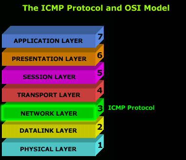
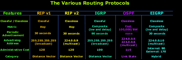
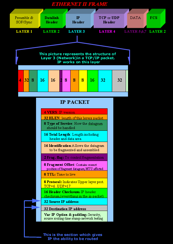
 There is a great amount of protocols covered on Firewall.cx, these include: IP protocol, Subnetting, TCP/UDP protocol, ICMP, DNS, FTP, TFTP, Netflow, Spanning Tree Protocol, Ethernet, RIP, OSPF and many more.
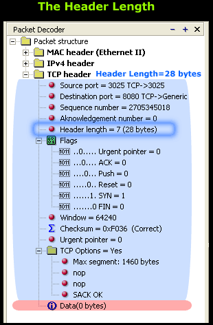


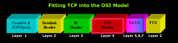
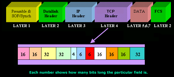
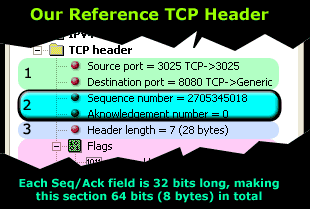
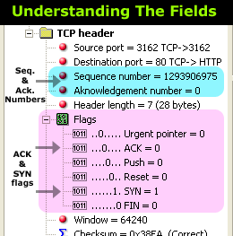
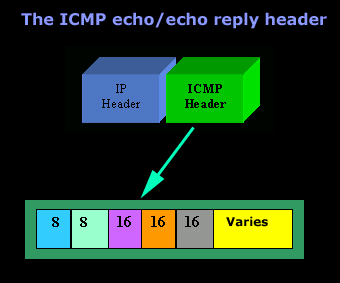
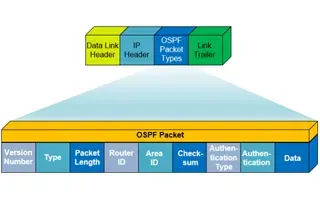
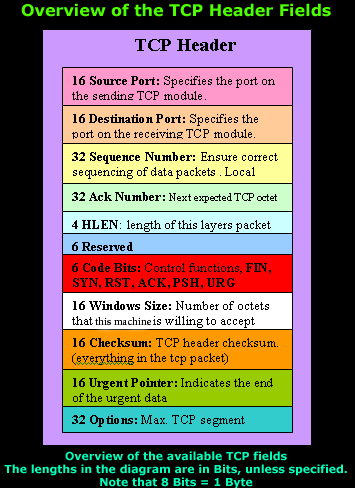 The diagram on the left shows the individual breakdown of each field within the TCP header along with its length in bits.
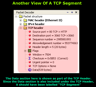
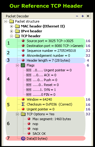 As you can see, the TCP header has been completely expanded to show us all the fields the protocol contains. The numbers on the right are each field's length in bits. This is also shown in the
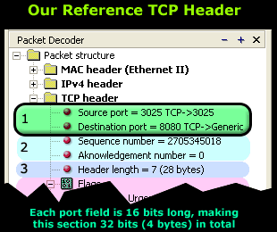


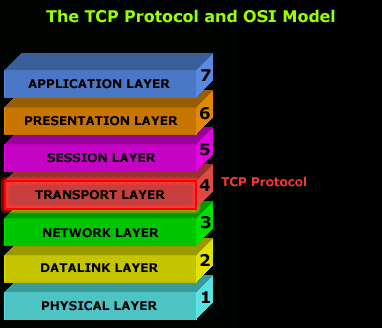
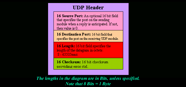
 protocol used at the Transport layer is UDP. Application developers can use UDP in place of TCP. UDP is the scaled-down economy model and is considered a thin protocol. Like a thin person in a car, a thin protocol doesn't take up a lot of room - or in this case, much bandwidth on a network.
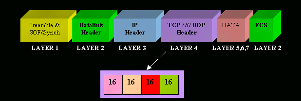


 We should note that the Bridge Priority Field can only be set in increments of 4096. This means that possible values are: 4096, 8192, 12288, 16384, 20480, 24576, 28672, 32768 etc. By default, Cisco’s Per-VLAN Spanning-Tree Plus (PVST+) adds this System ID Extension (sys-id-ext) to the Bridge Priority.
 Spanning Tree Protocol, Rapid STP port costs and port states are an essential part of the STP algorithm that affect how STP decides to forward or block a port leading to the Root Bridge.


 - The Reason For STP") One of the most used terms in network is LAN (Local Area Network). It’s a form of network that we encounter in our daily lives, at home, at work, study, and in various other areas of life. Unless working specially in the field of Wide Area Networks (WAN), you will come across a LAN pretty much everyday. A key protocol used to maintain efficiency within a LAN is the Spanning Tree Protocol (STP), which is standardized as
One of the most used terms in network is LAN (Local Area Network). It’s a form of network that we encounter in our daily lives, at home, at work, study, and in various other areas of life. Unless working specially in the field of Wide Area Networks (WAN), you will come across a LAN pretty much everyday. A key protocol used to maintain efficiency within a LAN is the Spanning Tree Protocol (STP), which is standardized as 
 SNMP (Simple Network Management Protocol) and


 Capacity planning with ManageEngine


 In our


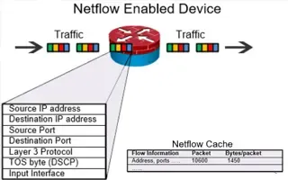
 Monitoring network traffic & bandwidth usage via Netflow is mandatory for any type and size network. Gaining visibility into user traffic, application traffic and data flows allows network engineers, administrators and security specialists detect bottlenecks – network congestion, unusual traffic patterns, monitor SLA agreements with providers, verify bandwidth availability, detect Quality of Service (QoS) issues, Wi-Fi Network monitoring, plus much more.


 It's easy to see why
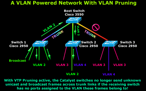
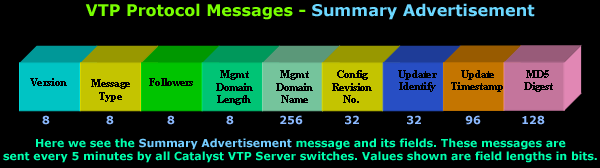
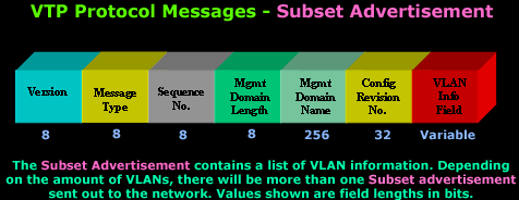
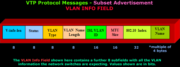
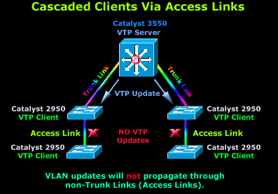
 VTP (VLAN Trunking Protocol) pruning is a feature that is used in Cisco switches to reduce unnecessary traffic in VLAN (Virtual Local Area Network) trunks. When VTP pruning is enabled on a trunk, the switch will stop forwarding broadcast, multicast, and unknown unicast traffic to VLANs that do not have any active ports.
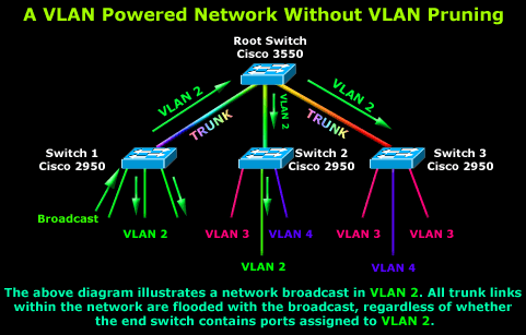

 The
The 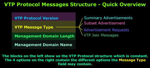

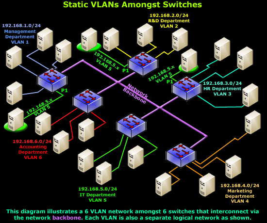
 The invention of VLANs was very much welcomed by all engineers and administrators, allowing them to extend, redesign and segment their existing network with minimal costs, while at the same time making it more secure, faster and reliable!
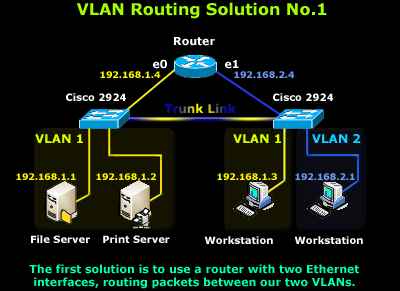
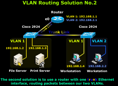
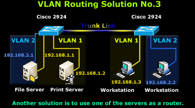
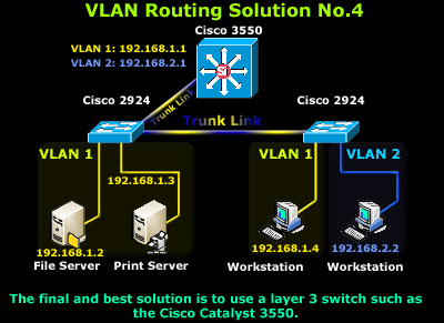
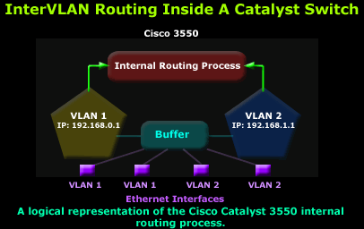
 This article deals with the popular topic of InterVLAN routing, which is used to allow routing & communication between VLAN networks. Our article analyses InterVLAN routing and provides 4 different methods of InterVLAN routing to help understand the concept
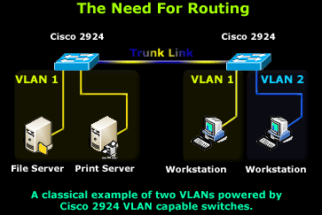
 While the
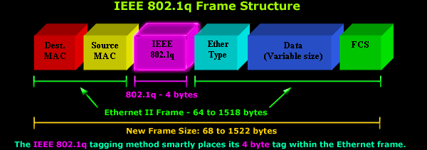


 Deciding whether to use ISL or
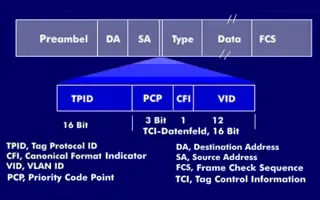
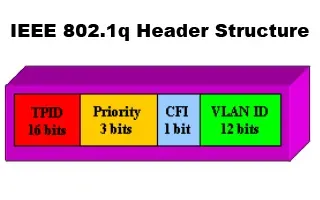
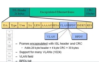
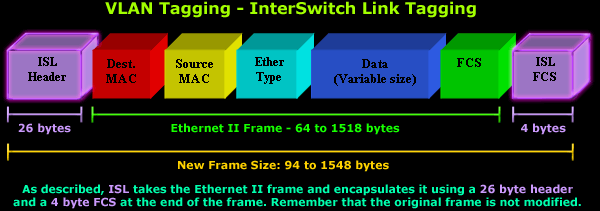
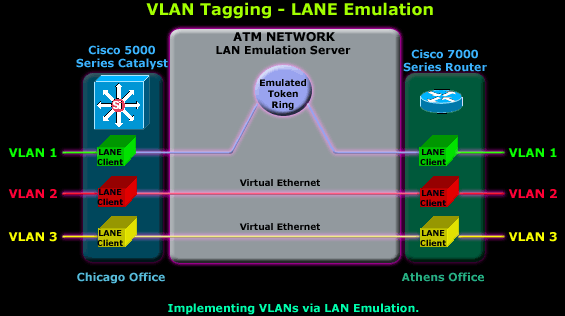
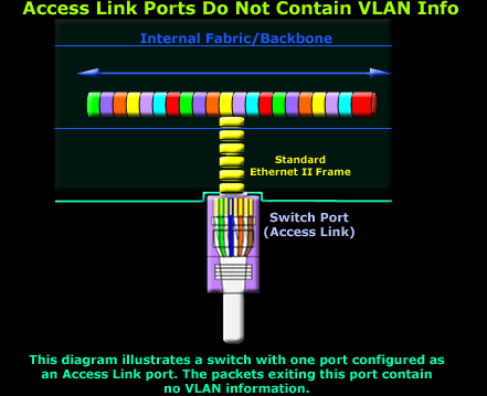
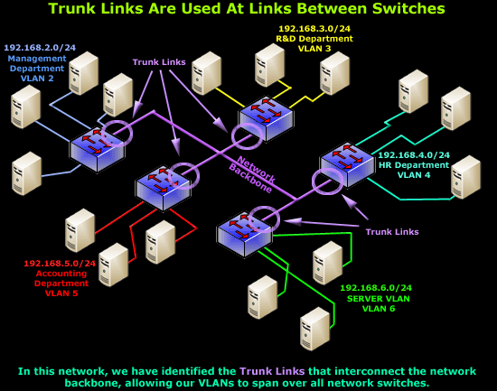
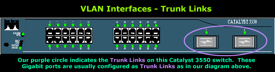
 We mentioned that Trunk Links are designed to pass frames (packets) from all VLANs, allowing us to connect multiple switches together and independently configure each port to a specific VLAN. However, we haven't explained how these packets run through the Trunk Links and network backbone, eventually finding their way to the destination port without getting mixed or lost with the rest of the packets flowing through the Trunk Links.
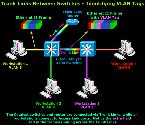


 If you've read our previous article

 Dynamic VLANs were introduced to grant the flexibility and complexity(!) that Static VLANs did not provide. Dynamic VLANs are quite rare because of their requirements and initial administrative overhead. As such, most administrators and network engineers tend to prefer Static VLANs.
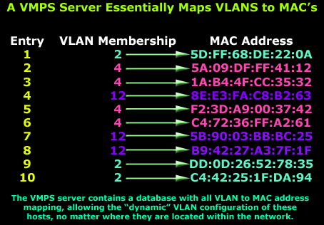

 VLANs are usually created by the network administrator, assigning each port of every switch to a VLAN. Depending on the network infrastructure and security policies, the assignment of VLANs can be implemented using two different methods: Static or Dynamic memberships - these two methods are also known as VLAN memberships.
 Designing and building a network is not a simple job. VLANs are no exception to this rule, in fact they require a more sophisticated approach because of the variety of protocols used to maintain and administer them.
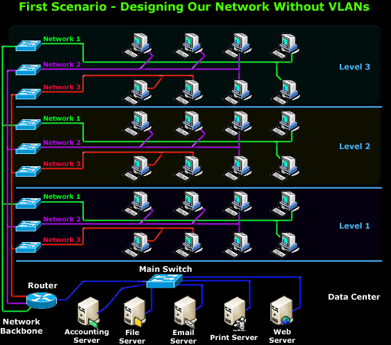
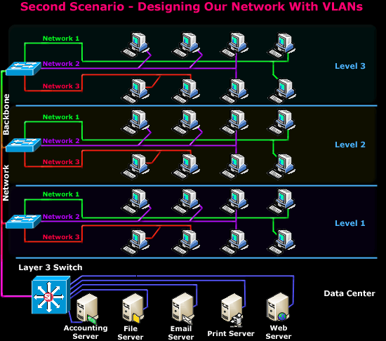

 We hear about them everywhere, vendors around the world are constantly trying to push them into every type of network and as a result, the Local Area Network (LAN) we once knew starts to take a different shape. And yet, for some of us, the concept of what VLANs are and how they work might still be a bit blurry.


 Figure 6. LSA Type 5 packets advertise the default route to all OSPF routers
 packet containing a Link State Advertisement (LSA)")


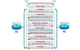

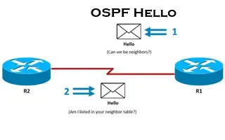
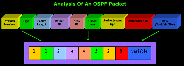
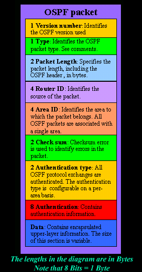
 This is the thrid article of our 6-part OSPF series (see below) that describes how OSPF routers perform neighbor relationship and adjacency. We’ll examine how OSPF discovers neighbors by sending Hello packets through the router interfaces and how it shares Link State Advertisements (LSAs) to form adjacencies and build its topology table. We’ll also examine the contents of OSPF Hello packets (Router ID, Hello/Dead Intervals, Subnet Mask, Router Priority, Area ID, DB & BDR IP Address, Authentication information) and more.
")
 and R2 Acknowledges with a LSAck")
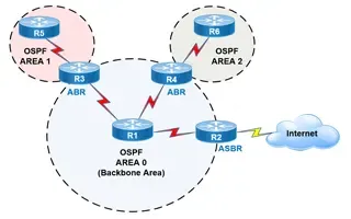
 This article covers basic OSPF concepts and operation. We explain how OSPF works, how OSPF tables are built on an OSPF-enabled router and their purpose (Neighbour Table, Topology Table, Routing Table), OSPF areas and their importance. Next we cover OSPF Link State Packet types used to exchange data between OSPF routers: Link State Advertisement (LSA), Link State Database (LSDB), Link State Request (LSR), Link State Update (LSU) and Link State Acknowledgment (LSAcK).
, ABR and ASBR OSPF routers")
 This article shows how to configure and setup SSH for remote management of Cisco IOS Routers. We’ll show you how to check if SSH is supported by your IOS version, how to enable it, generate an RSA key for your router and finally configure SSH as the preferred management protocol under the VTY interfaces.
 Figure 1. Understanding Basic Embedded Packet Capture Terminology
 Figure 2. Capturing packets betwen host 192.168.3.2 and Firewall.cx
 Figure 3. Importing packets into a Network Analyzer
 Figure 4. Packets displayed inside the network analyzer
 Chances are we’ve all needed to upgrade our Cisco’s device IOS software at some point. While upgrading the IOS software on a Cisco device is considered to be a fairly simple process, it can turn out to be a very stressful and destructive process if something goes wrong, especially if the upgrade is being performed on a remote Cisco device. Uploading a corrupt IOS image or having it become corrupt during the upload process is a common problem Cisco engineers encounter.


 Display/Window View Problem - Internet Explorer 10 Not Showing Correctly")
 Display Problem - Internet Explorer Compatibility View Settings")

 Display/Window View Problem - Internet Explorer 10 Settings")
 Display/Window View Problem - Internet Explorer 10 Settings")


 Figure 1. The tftp source IP problem with tftp and other services on a Cisco Router


 Configuring PPP Multilink is a pretty straightforward process, however, configuration steps can differ depending on the interfaces and protocols you are dealing with.
 The above diagram illustrates a typical MPLS VPN network where VRFs are unique for each VPN connected to a particular Provider Edge router


 Typical Man-in-the-Middle attack. Client data streams flow through the attacker


 This article explains the procedure that should be followed to correctly shutdown/powerdown a Cisco Nexus 7000 series module and remove it from the chassis. We also include important tips that will help ensure you avoid common problems and mistakes during the removal procedure.


 Our previous article shows how to perform a
  This article shows how to reset a password on a Cisco Catalyst 3750-X (stacked or single unit) and Cisco Catalyst 3560-x switch without losing its startup configuration. The Cisco password recovery procedure involves interrupting the switch’s normal boot procedure, renaming the flash:config.text (that’s the startup-config file for switches) to something else e.g flash:config.text.old so that the configuration file is skipped during bootup.
 In previous articles, we showed how it is possible to
  This article covers basic and advanced configuration of Cisco Catalyst Layer-3 switches such as the Cisco Catalyst 3560G, 3560E, 3560-X, 3750, 3750E, 3750-X, 3850, 4500, 6500 , 9300, 9400 series, and extends to include the configuration of additional features considered important to the secure and correct operation of these devices.
 Due to Cisco’s new licensing model, purchasing a Layer 3 switch doesn’t really mean that essential features such as InterVLAN routing can be used.


 There’s a new switch around the block and its name is Catalyst 3850 – Cisco’s latest addition to its successful Catalyst series switches. The Cisco Catalyst 3850 is no ordinary switch – it’s fully stackable and designed to integrate wired and wireless networks by offering full switch and the industry’s first built in wireless LAN controller.

 Configuration") Figure 1. The network diagram above helps us understand the terminology and implementation of SPAN.
Figure 1. The network diagram above helps us understand the terminology and implementation of SPAN.

 The Cisco Catalyst Switching Portfolio is perhaps one of the most useful Cisco PDF files, containing all Catalyst series products.


 configuration")


 Errdisable is a feature that automatically disables a port on a Cisco Catalyst switch. When a port is error disabled, it is effectively shut down and no traffic is sent or received on that port.
 Many companies are seeking for Cisco SFP alternatives to help cut down the costs on these expensive modules.
 This article focuses on VLAN Security and its implementation within the business network environment. We provide tips and Cisco CLI commands that will help you upgrade your VLAN network security.


 This article explains how to configure a Cisco Firepower 2100 series device to operate in Appliance mode. We’ll show you how to switch from Platform mode to Appliance mode and how the device will automatically convert and retain your ASA configuration.
")


 The Cisco ASA Firewall 5500-X series has evolved from the previous ASA 5500 Firewall series, designed to protect mission critical corporate networks and data centers from today’s advanced security threats.
 provide advanced key security features to ASA Firewalls")
 Figure 3. The Cisco FireSIGHT Management Center Graphical Interface
 Cisco’s Adaptive Security Appliance (ASA) Firewalls are one of the most popular and proven security solutions in the industry. Since the introduction of the PIX and ASA Firewall into the market, Cisco has been continuously expanding its firewall security features and intrusion detection/prevention capabilities to adapt to the evolving security threats while integrating with other mission-critical technologies to protect corporate networks and data centers.
 Figure 2. The Cisco ASA Firewall AIP SSC-5, AIP SSM-20 and AIP SSM40 IPS hardware modules
")
")

 In late 2014, Cisco announced the new licensing model for the latest AnyConnect Secure Mobility client v4.x. With this new version, Cisco introduced a number of new features, but also simplified the licensing model which was somewhat confusing. In this article, we will take a look at the new AnyConnect 4.x licenses which consist of: AnyConnect Plus license, AnyConnect Plus Perpetual license and AnyConnect Apex license.
 The Cisco ASA 5500 series security appliances have been around for quite some time and are amongst the most popular hardware firewalls available in the market. Today Firewall.cx takes a look at how to easily setup a Cisco ASA5500 series firewall to perform basic functions, more than enough to provide secure & restricted access to the Internet, securely access and manage the ASA Firewall and more.
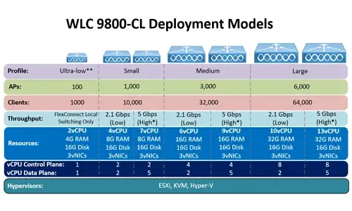
 This article covers the deployment of the Cisco WLC 9800-CL cloud-based controller on the VMware ESXi platform. We explain the CPU, RAM and storage requirements, provide URLs to easily download and install the WLC controller using the OVA template, select the appropriate WLC 9800 deployment size (small, medium, large) and help you understand and configure the different WLC VM network interfaces.
 This article explains how to convert a local or remote Autonomous / Standalone Cisco Aironet Access Point to Lightweight and register it to a


 Figure 1. Available Ports on a Cisco WLC 5500
 Figure 2. Picture of Fiber & Ethernet Copper SFPs
 Figure 3. Pictures of WLC2504 & WLC2124

 Figure 1. A few of the larger Cisco WLC models and Catalyst 3850
 Figure 2. Cisco WLC 8500 (left) and Cisco WLC 2500 (right) web interface


 We would like to inform our readers that Firewall.cx has just made available as a free download all of


 Cisco Unified CallManager (CUCM) and its Voice Gateway relies on the telecommunication provider (telco) to send the correct call details for every incoming call, to allow the system to correctly process it and route it.
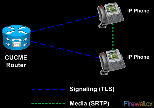 Figure 1 - CUCME to Cisco IP Phone SRTP and TLS
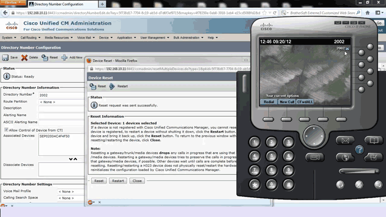
 Factory Reset Procedure & Password Recovery") This article explains how to reset your Cisco 7940, 7941, 7942, 7960, 7961, 7962 & 7920 IP phone to factory defaults, and how to upgrade its firmware to the latest available version.
This article explains how to reset your Cisco 7940, 7941, 7942, 7960, 7961, 7962 & 7920 IP phone to factory defaults, and how to upgrade its firmware to the latest available version.
 This article explains how to reset your Cisco 7945, 7965 and 7975 IP phone to factory defaults, and how to upgrade the firmware to the latest available version. We also provide necessary information on how to setup a DHCP server on a CME router or Cisco Catalyst switch, to support Cisco IP Phones and provide them with DHCP Option 150 so they know where to find and register with the CallManager or CallManager Express server.

 Let’s now understand the threats that lurk around your UC solution and could possibly prove detrimental to the operations of a UC network.
 Cisco is continuously developing its CallManager Express product, introducing new features and services to help keep up with its customers' and the market’s demands.


 This article shows how to perform an ISSU (In-Service Software Upgrade) on a
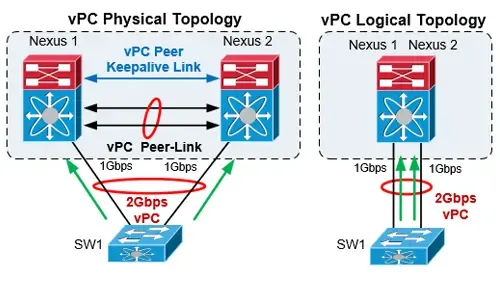

 Whether you’re new to
  The output from NX-OS show commands can be lengthy and that makes it difficult to find the information we are looking for. The Cisco NX-OS software provides the means to search and filter the output to assist in locating the information we are after.
  Nexus switches offer powerful scripting capabilities since integrating Python into NX-OS and can simplify network operations through the ability to run Python scripts directly on the switch. Python is a powerful programming language with a simple approach to object-oriented programming. The Cisco Nexus 5000 series switches with Releases 5.2(1)N1(1) and later and the Cisco Nexus 6000 series switches with Releases 6.0(2)N1(1) and later, support all the features available in Python v2.7.2. The Cisco Nexus 7000 series also support Python v2.7.2 and the Cisco Nexus 9000 Series devices support Python v2.7.5. The python scripts can be used to execute configuration commands, show commands, parse CLI output, call other scripts etc.
 The Cisco NX-OS checkpoint feature provides the capability to capture at any time a snapshot (backup) of the Cisco Nexus configuration before making any changes. The captured configuration (checkpoint) can then be used to roll back and restore the original configuration.
 This article introduces the Cisco Nexus product family (Nexus 9000, Nexus 7000, Nexus 5000, Nexus 3000, Nexus 2000, Nexus 1000V and MDS 9000). We explain the differences between Nexus and Catalyst switches but also compare commands, naming conventions, hardware capabilities etc. between Nexus NX-OS and Catalyst IOS operating systems. To provide a comprehensive overview we explain where each Nexus model is best positioned in the Data Center and directly compare high-end Nexus switches (Nexus 9000/7000) with high-end Catalyst switches (Catalyst 6800 / 6500) examining specifications, bandwidth – capacity, modules and features (High-Availability, Port Scalability, VDC, vPC – VSS, OTV, VXLAN, etc).


 It’s a reality – Australia now has its own Official Cisco Data Center User Group (DCUG) and it’s growing fast! Originally inspired by Cisco Champions Chris Partsenidis and Derek Hennessy, the idea was fully backed by Cisco Systems as they happened to be looking to start up something similar on a global scale.


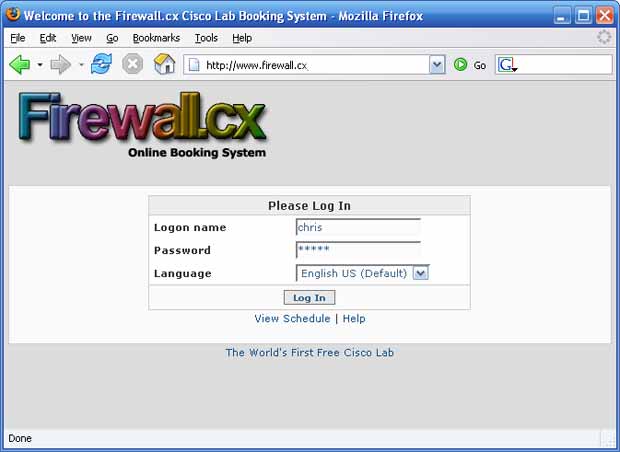
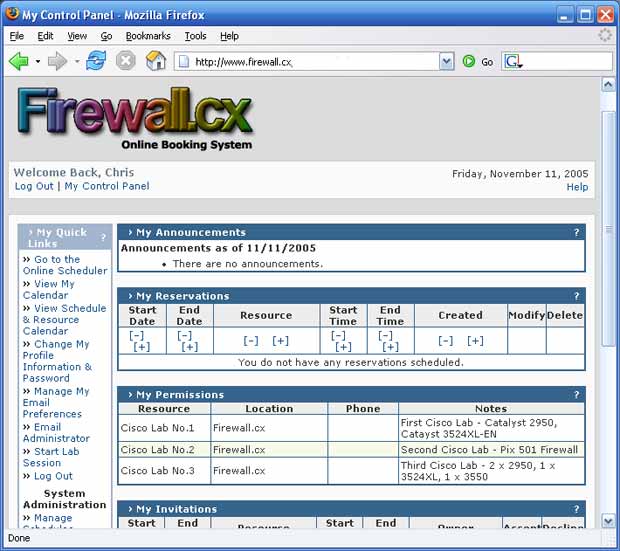
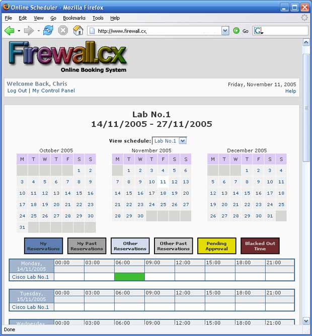
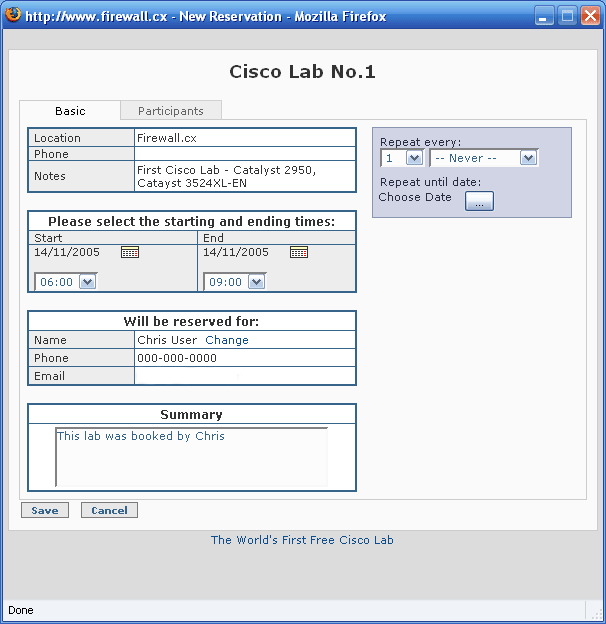
 One of the most difficult things for people who are starting out in a networking career is getting their hands on the equipment. Whether you are studying for Cisco certification or just wanting to test certain network behaviors in a lab, no one would argue that practicing is the best way to learn.


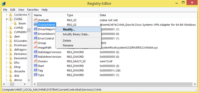
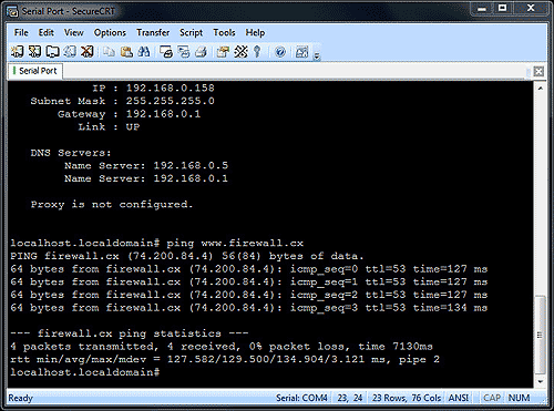
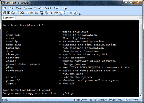
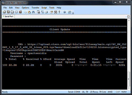
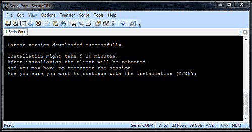
 This article shows to how correctly install Cisco VPN Client (32 & 64 bit) on Windows 10 (32 & 64 bit) using simple steps, overcome the ‘This app can’t run on this PC’ installation error, plus fix the Reason 442: Failed to enable Virtual Adapter error message. The article applies to New Windows 10 installations or Upgrades from earlier Windows versions and all versions before or after Windows 10 build 1511. We also include all required VPN files directly downloadable from Firewall.cx to save time and trouble from broken 3rd-party links.


")
")
")
")
")
")
")
")
")
")
")
")
")
")
")
")
")
")
")
")
")
")
")
")
")
")
")


 Unified communications is a very popular term these days and we see it appearing on almost every vendor as they rename their platforms and products to include this term. The definition of unified communications changes slightly depending on the vendor you are looking at, but its foundation remains the same. Breaking unified communications into components makes it a lot easier to analyze and put things into the correct perspective.
 - Reason 442: Failed To Enable Virtual Adaptor - How To Fix It")


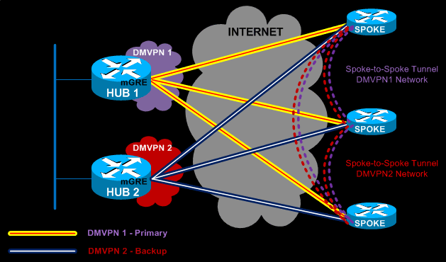
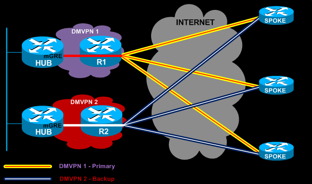

 mGRE Tunnel Interface is used to allow a single GRE interface to support multiple IPSec tunnels and helps dramatically to simplify the complexity and size of the configuration.
 Each GRE tunnel between the hub-spoke routers is configured with its unique network ID. For example, GRE tunnel between the HUB and Remote Office 1 could use network 10.0.0.0/30, while GRE tunnel between the HUB and Remote Office 2 could use 10.0.1.0/30 etc.
 Unfortunately the good old 'remove and reinstall' method won't get you far in this case as the problem is not within the Cisco VPN client program, but Microsoft's Internet Connection Sharing (ICS) service.

 Discover the ins and outs of using Palo Alto Networks’ Software NGFW (Flex) credits to seamlessly renew your cloud-based or virtualized software NGFW devices! Dive into this exciting guide where we unravel the mysteries of software NGFW credits, show you how they're allocated to your deployment profile, and walk you through the renewal and verification process.
 This article’s purpose is to help you quickly master Palo Alto QoS concepts and learn to configure QoS on Palo Alto Firewalls in a simple and efficient way. QoS is considered a complicated topic however thanks to Palo Alto’s intuitive firewall GUI interface and our real-scenarios, you’ll quickly grasp all necessary QoS basics and be ready to implement your own QoS policies!
 QoS Priority Queues - Packet classification and prioritization
 This article provides comprehensive guidance on the manual processes involved in downloading, uploading, and installing (import) any PAN-OS version on a Palo Alto Firewall. It details the steps for searching and downloading the desired PAN-OS version, as well as the supported methods for uploading the software to your Palo Alto Firewall, including Web, TFTP, and SCP. Additionally, the article offers valuable tips aimed at facilitating a smooth and successful upgrade process.
 This article will show you how to configure an IPSec VPN tunnel between a Palo Alto firewall (all PANOS versions) and Meraki MX security appliance. Our comprehensive guide includes IPSec VPN setup for static & dynamic IP endpoints, Full tunnel VPN configuration, Split tunnel VPN configuration, special considerations for Full & Split tunnel modes, IPSec Phase 1 - IKE gateway & crypto policies, IPSec Phase 2 – Tunnel encryption algorithms & authentication plus more.


 Keeping your Palo Alto Firewall up to date with the latest PAN-OS software updates is an important step to ensure your organization is protected against the PAN-OS latest software vulnerabilities, software bugs but at the same time take advantage of Palo Alto’s latest security enhancements and capabilities.


 During the past decade, we’ve seen the global IT security market flooded with new network security and firewall security appliances. New vendors emerging into the market while existing well-known vendors introduce new smarter and complex firewalls that aim to keep enterprise organizations as safe as possible. Palo Alto Networks is one of the new-generation security vendors who have managed to break into a saturated market and make their stand.

 The digital transformation is pushing applications to the cloud, the 2020-2022 pandemic shifted employees to work from home, and the number of resulting new use cases is sending IT leaders scrambling for answers. The number of solutions IT departments have had to adopt to ensure their network's performance and security has continuously grown for over a decade.


 Secure Access Service Edge (SASE) is an architecture widely regarded as the future of enterprise networking and security. In previous articles we talked about the
  Global connectivity is top of mind for many IT teams at organizations of all sizes. We are currently in the middle of a dramatic shift in business and technology practice, as users are becoming more mobile while applications are being transitioned to the cloud. This shift will only accelerate as companies will look to leverage the speed and agility of cloud services with the operational, cost and quality advantages of a geographically distributed work force. While Covid-19 has contributed to the acceleration of this shift, the change was always inevitable once technology was ready. Legacy connectivity and security products have long been a barrier to progress.


 This article explores the need for Secure Access Service Edge (SASE) in today’s organizations. We show how one of the most advanced SASE platforms available, combines


 The Virtual Private Network (VPN) has become the go to security solution for keeping communications between networks and endpoints secure. After all, VPNs offer a straightforward, secure method for connecting sites (a

 Software Defined Wide Area Networking (SD-WAN) is changing the way that businesses connect to the cloud. With SD-WAN, organizations can move away from closed, proprietary hardware solutions, bringing flexibility and potential cost savings to their operations.

 Enterprises have been successfully running WAN optimization appliances at their many distributed sites for years. The devices have done a good job of helping businesses squeeze as much capacity as possible out of their WAN links and to improve performance across low-bandwidth, long-distance network circuits.
 While historically most application requests were directed inward, toward corporate data centers, most are now outbound, toward cloud and Internet locations. As the software as a service (SaaS) computing model continues to gain steam, these trends will only get stronger.
 With so much enterprise network traffic now destined for the cloud, backhauling traffic across an expensive MPLS connection to a data center to apply security policy no longer makes sense. Software-defined WANs (SD-WAN) promise lower transport costs with direct, higher-performing connections to cloud and Internet resources. But what are the security implications of moving traffic off of private MPLS VPNs and onto public broadband links?

 A lot has changed in how people work during the past twenty years. Co-working spaces, mobility, and the cloud now are common. Businesses are spread out and branch offices are empowered.
 By: Shlomo Kramer, Check Point Software & Cato Networks Co-Founder


 The Wide Area Network (WAN) is the backbone of the business. It ties together the remote locations, headquarters and data centers into an integrated network. Yet, the role of the WAN has evolved in recent years. Beyond physical locations, we now need to provide optimized and secure access to Cloud-based resources for a global and mobile workforce. The existing WAN optimization and security solutions, designed for physical locations and point-to-point architectures, are stretched to support this transformation.


 SD-WAN is the answer for enterprises and organizations seeking to consolidate network functions and services while at the same time simplify their WAN infrastructure and its management.

")


 This article explores the Security Service Edge (SSE) portion of Secure Access Service Edge (SASE) and the need for holistic cybersecurity protections.
 fits into SASE’s Security Pillars")

 The newest release of the Acunetix Web Vulnerability Scanner further improves performance and premieres best-of-breed technologies.
 SQL injection vulnerabilities have held the first spot on the


 With nearly every business sector relying on the internet and digital tools to function, it is no surprise that cybersecurity is the second-fastest growing industry. Hackers don’t care how large or small your company is. They will target all sizes in an all-out effort to steal data, access confidential or classified information, cause mayhem, and hurt the organization's reputation.
 Organizations with unimpressive IT budgets may be tempted to minimize how much they spend on security-related tools, activities, and training due to the challenge to mathematically determine what the return on investment (ROI) will be. If one thing is certain, it’s that management will want to know the ROI and when cyber-attacks are in play, coming up with an accurate representation of how much a successful penetration could have cost is, well, not easy.
 There are two primary approaches to web application security testing. Dynamic Application Security Testing (DAST), also called black box testing, imitates an attacker.
 works")
 A gray box testing solution adds hooks around key calls (for example, database calls, system calls, etc.). Those hooks, often called sensors, communicate two ways with the IAST scanner. Hooks do not require access to the source code. The scanner works directly with the interpreter or the application server.

 Security researchers disagree about the percentage of vulnerable websites, but most concur that it’s way too high. Despite their long history, attackers continue to use


 Acunetix DeepScan and the Acunetix Login Sequence Recorder have been updated to support ECMAScript version 6 (ES6) and ECMAScript version 7 (ES7). This allows Acunetix to better analyse JavaScript-rich sites which make use of the latest JavaScript features. The modularity of the new Acunetix architecture also makes it much easier now for the technology to stay ahead of the industry curve.

 SQL Injection Attacks are one of the most popular attacks against web servers, websites and web applications. A fairly popular website can expect to receive anywhere between 80 and 250 SQL injection attacks on a daily basis and these figures can easily reach thousands when an SQL vulnerability is disclosed to the public.
 A web application would typically communicate with a variety of back-end systems, including a database. Let’s take an HTML form, which inserts values into a database, as an example.
  Acunetix has refreshed its online web and network vulnerability scanner, Acunetix Online, with a massive update. The new Acunetix Online now incorporates all the features found in its on premise offering, Acunetix On Premise. With a brand new simpler than ever user interface, integrated vulnerability management and integration with popular Web Application Firewalls (WAFs) and Issue Tracking systems, this is by far the biggest Acunetix Online release since it’s introduction.
 This article aims to help you understand how
 Figure 1. Illustration of how CSRF attacks work
 According to Wikipedia, security is defined as the degree of resistance to, or protection from, harm. It applies to any vulnerable and valuable asset which in almost all cases, will include an organizations’ website, web service and IT infrastructure.
 Figure 1. Generating ModSecurity Rules from a Web Application Vulnerability Scanner
 This article examines the differences between logical and technical web application vulnerabilities which tends to be a very confusing topic especially for web application developers and security – penetration experts because it would make sense that a vulnerability by any other name is simply confusing something that should be simple.
 Technical vulnerabilities is an area where automated scanners excel — it is a rule-based process. It is also time intensive, because of the vast number of attack vectors and potential vulnerabilities. For a human to complete this process, while possible, would be extremely expensive and likely full of both false-positives and false-negatives.
 Logical vulnerabilities are much harder to detect primarily because they require a human to think about and assess a potential problem. While it’s true that some logical vulnerabilities can be programmed, it’s often cost-prohibitive to do so.
 In this article, we’re going to talk about automating your web security in the safest and most effective way. We’ll also touch on a few Web Application Security automation tools worth considering using. Furthermore, we'll speak about why its important to select the right Web Application Scanning tool and how it can help meet your web development time frame, saving the company a lot of money and time.
 You might be asking, “how can an automated web vulnerability scanner possibly replace a human?” You’d be correct in your assumption that an automated scanner is no replacement for human intuition or experience. However, you’d probably also agree that manually scanning for hundreds or thousands of
  Successful web application attacks and the data breaches that are resulting from these attacks, have now become everyday news, with large corporations being hit constantly.
 One such example of implementing a defense in depth approach would be to restrict an administrator panel to be accessed only from a particular IP address. Even though there is enough protection, for most cases, by using credentials in the form of a username and password to log into the admin panel, the added layer of protection will come in handy. If the password is disclosed to an attacker, the protection will no longer be valid, therefore making the login setup irrelevant. By implementing another small but robust security feature, you will be moving towards making your defense infallible.
 Part two of our Cross-site scripting (XSS) series shows how easy it is to create & execute a XSS attack, helping readers & network security engineers understand how XSS attacks work and how to identify web application vulnerabilities.
  This is also only one example of the various kinds of XSS attacks that can be executed. XSS attacks fall into three general categories as defined by OWASP: Stored, Persistent XSS, Reflected, and DOM-based XSS. Stored XSS attacks, as their name implies, are stored unsanitized in the website (such as in a database entry) and rendered on page-load (this is how the Samy worm operated). Reflected XSS attacks are usually more common, often a result of data within an unsanitized URI string that is rendered by the website’s frontend code (such as in the example above). The final type, DOM-based, exploits the Document Object Model environment similar to a reflected XSS attack, but by altering the page’s elements dynamically.
 Part one of our two-part series on Cross-site scripting (XSS) explains what are XSS attacks. We also take a close look on how XSS exploits work (urls, cookies, web cache etc.) and analyze their impact on business websites – webservers, using real examples of popular sites that were hit using different XSS exploits. We also talk about the different type of XSS attacks that make website users very difficult to identify and detect them. Part-two will provide a Cross-site scripting attack example, talk about the different type of XSS vulnerabilities and explain how to identify XSS vulnerabilities in your web applications & web servers.
 An XSS attack can actually be quite dangerous for users of a website, and not just because of the possible trust lost from its customers. When a user accesses a website, often much of its content is hidden behind some form of authentication – like how Facebook is practically useless unless you have an account. That authentication not only hides privileged information, but also provides access to the account itself (social media information, ability to make purchases, etc.). Some of the information required for that authentication is stored on the user's computer, namely in the form of cookies. If a user's cookies can be compromised via an injected XSS exploit, their account can be hijacked as well.
 StrongVPN is one of the most popular


 Back then, the Internet was so very young. Those were the times of Windows Maze Screensaver, of the classy Minesweeper, of grey-white MS Paint, and of silvery floppy disks. Gone are those days. Now, after completing its silver jubilee, the Internet has grown to be almost a multiverse of information, every micro-second its network mushrooms like anything. But even maturity comes with its own struggle. This enhanced version of the Internet carries its own privacy concerns.
 TOR or The Onion Router is a free, open source software that comes under the development and maintenance of The Tor Project, a non-profit organisation funded by the US Government. TOR enables users to preserve their anonymity over Internet communications.


 The internet is in a strange place right now. It’s no longer the open, free place it used to be. Increasingly, users are being subject to website blocks, attacks, and surveillance. For true safety or anonymity, precautions must be taken. Thankfully, there many ways for you to protect yourself, one of them being Socket Secure (SOCKS) proxies.


 Despite what some think, the internet is not private. Anonymous browsing and Internet Privacy are almost non-existent in today's online world. Websites collect personal information on every visit without your knowledge. Despite the free label, services come at a cost, and in many cases, it’s a lack of privacy.


 VPN (Virtual Private Network) is a well-known acronym amongst regular internet users. Initially used within businesses to securely connect to the corporate network, nowadays it’s being used by almost any type of user for anonymous browsing, protecting their privacy and stopping ISPs and government agencies tracking their online activities and transactions who are looking to capture users performing illegal file sharing of movies, music albums, torrenting or even trying to access geo-restricted content such as Netflix, Hulu and other streaming services.


 It’s hard to go to a pub, café, or hotel these days without running into public or guest WiFi. In many cases, an internet connection can feel like a necessity – keeping up with work or personal emails, arranging plans with friends, checking social media. Connecting is usually as easy as entering an email address, filling out a survey, or entering a code on a receipt.

 Hotels are one of the most vulnerable places for such attacks. They often have hundreds of people connected to the network at a time and hackers can stay in their rooms, undetected by anyone. Most hotels don’t have good security, and standardization means that many have the same, vulnerable hardware.


 Encrypted communication has the add-on effect of avoiding bandwidth throttling from ISPs. As mentioned earlier, service providers inspect packets to classify different data. This lets them put a speed cap on specific mediums. This is usually done unofficially and some service providers will deny the practice despite significant data


 It was just a matter of time until the new global wave of government site blocking at the ISP level arrived in Australia. In mid-December 2016, the


 Despite innovations in security and technology, it’s difficult to remain anonymous online. Identifying information is seemingly everywhere – from malicious JavaScript tracking to the location services in web browsers. Even secure


 VPN Services have become a necessity for users concerned about their online privacy and security. With literally hundreds of thousands of attacks daily, exploits and security vulnerabilities being discovered plus government agencies and ISPs monitoring user activity, the internet is no longer considered a safe place.


 Businesses of all sizes are more and more adopting cloud-based platforms like Microsoft 365 to streamline operations, improve collaboration, and increase productivity. However, this newfound reliance on such software solutions makes these businesses prime targets for cybercriminals.
 One of the most critical security solutions within the Microsoft 365 ecosystem is Microsoft Defender for Office 365. This tool is specifically designed to protect against email-based threats such as phishing, malware, and ransomware, which are common attack vectors targeting businesses.
 Data breaches and cyber threats cast a long shadow over both organizations and individuals alike, making the need for robust cyber security measures more pressing than ever. However, the most advanced technology in the world cannot fully protect against cyber risks if the people using it are not aware of the dangers and the best practices for avoiding them.
 Cyber security awareness encapsulates the knowledge and behaviors that individuals within an organization adopt to protect its information assets. It's not merely about having the right technology in place; it's about ensuring every member of the organization understands the role they play in maintaining security. This understanding spans recognizing potential threats, such as
 This article serves as a comprehensive guide to fortifying the security posture of Microsoft 365, covering essential aspects ranging from foundational security principles to advanced strategies for optimizing productivity without compromising security. From introducing the fundamental
 This article provides a comprehensive guide to deploying Active Directory and DNS Services on Windows Server 2022, encompassing the Essential, Standard, and Datacenter editions. Our guide also includes step-by-step instructions for promoting the Windows server to a Domain Controller (DC). To enhance user experience, we've included plenty of helpful screenshots, ensuring a smooth and uncomplicated installation process.


 A Windows Active Directory Certification Authority server (AD CA), also known as a Certificate Authority, is an essential service to every organization’s Active Directory as it can manage, issue, revoke and renew digital certificates used to verify the identity of users, computers and other network services.


 If your organization is planning to migration from a Hyper-V virtualization environment to VMware then this FREE webinar is just for you.
 One of Windows Server 2016 highlights is the newer Hyper-V server that not only extends the hypervisor’s features and capabilities but also introduces a number of new enhancements and concepts that take virtualization to a new level.
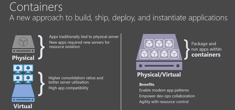


 This article describes the new Windows Server 2016 Licensing model (per-core licensing) Microsoft has implemented for its new server-based operating system. While the


 The new Hyper-V virtualization features offered by Windows Server 2016 are planning to make major changes in the virtualization market. From Nested Hyper-V, revolutionary security, new management options to service availability, storage and more.

 Figure 3. Creating a new NIC Team in Windows Server 2012
 Figure 4. Configuring Teaming Mode, Load Balancing Mode and NIC Team members
 Figure 5. Viewing NIC Teams, their status, speed, Teaming mode, Load balancing mode and more
 Figure 6. The newly created NIC Team Adapter in Windows 2012 Server
 People and companies usually adopt a backup strategy suited to the needs of their working environment. As such, there is no absolute right or wrong method of backing up data however in order to backup and restore data swiftly and easily a comprehensive strategy is necessary, even though most virtualized platforms such as Hyper-V and VMware offer built-in backup-like features such as snapshots or ability to copy a whole virtual machine to another location.
 Users working with Hyper-V Virtualization would be interested to know that Altaro is hosting a free webinar on the 25th of February 2016 at 4pm CET / 10am EST. Microsoft Cloud and Datacenter Management MVPs Didier Van Hoye and Andy Syrewicze will be answering questions on how to fix a broken Hyper-V Host or Hyper-V Cluster and will also be sharing some tales from the trenches.
 incorrectly identifies the Private & Public networks on our network interface cards")


 As more companies around the world adopt the virtualization technology to increase efficiency and productivity, Microsoft’s Hyper-V virtualization platform is continuously gaining ground in the global virtualization market, as is the need for IT departments to provide rock-solid backup solutions for their Hyper-V virtualized environment.
 Figure 1. Installation Welcome Screen
 Figure 2. Altaro Hyper-V Installation Complete
 Figure 3. Connecting to the Hyper-V Agent Remotely
 There are umpteen reasons why your Windows Server 2012 R2 decides to present you with a Blue Screen of Death (BSOD) or the stop screen. As virtual machines become more prominent in enterprise environments, the same problems that plagued physical servers earlier are now increasingly being observed for crashes of virtual machines as well.


 available")


 Microsoft introduced Fine-Grained Password Policy for the first time in Windows Server 2008 and the policy has been part of every Windows Server since then. Fine-Grained Password Policy allows overcoming the limitations of only one password policy for a single domain. A brief example is that we apply different password and account lockout policies to different users in a domain with the help of Fine-Grained Password Policies.


 IT professionals frequently need connectivity and management tools. The Telnet Client is one of the most basic tools for such activities. Using this tool, you can connect to a remote Telnet server and run applications on it. This is also a very useful tool for testing the connectivity to remote servers, such as those running SMTP services, web services and so on. In this article we will discuss how to install or enable Telnet client for


 Microsoft Licensing for Virtual environments can become a very complicated topic, especially with all the misconceptions and false information out there. Thankfully Altaro, the leader in
 Figure 1. DNS Installation via Active Directory Services Deployment
 Figure 2. Selecting Role-based or feature-based installation
 Figure 3. Selecting the Server that will host the DNS server role
 Figure 4. Selecting the DNS Server Role for installation
 Figure 5. DNS Information
 Figure 6. Confirm Installation Selections
 Figure 7. Installation Progress
 Figure 8. DNS Manager & DNS Zones
 Figure 9. DNS Forwarders – Add your ISP or Public DNS Servers here
 Figure 10. Advanced Options - Scavenging
 Figure 11. Root Hints
 Figure 12. Monitoring Tab – Configuring Automated DNS Test Queries
 Figure 13. Event Logging
 Figure 14. Debug Logging – Capturing DNS Packets & Configuring DNS Debugging
 Figure 15. Zone Properties
 Figure 16. Start Of Authority Settings
 Figure 17. DNS Name Servers
 Figure 18. Zone Transfers
 The Domain Name System (DNS) is perhaps one of the most important services for Active Directory. DNS provides name resolution services for Active Directory, resolving hostnames, URLs and Fully Qualified Domain Names (FQDN) into IP addresses. The DNS Service uses UDP port 53 and in some cases TCP port 53 - when UDP DNS requests fail consistently. (Double-Check for Windows)
 Our previous article explained
 Figure
 Figure 1. GPO Objects
 Figure 2. Group Policy Settings
 Figure 3. GPO Scenario
 Figure 4. Open GPMC
 Figure 5. Select FW Users and Create a GPO
 Figure 6. Creating our Wallpaper Group Policy Object
 Figure 7. Editing a Group Policy Object
 Figure 8. Selecting and editing Desktop Wallpaper policy
 Figure 9. Configure Desktop Wallpaper
 Figure 10. User Login
 Figure 11. Computer Desktop Wallpaper Changed


 Hyper-V has proven to be a very cost effective solution for server consolidation. Evidence of this is also the fact that companies are beginning to move from VMware to the Hyper-V virtualization platform. This article will cover the Windows 2012 Hyper-V best practices, and aims to help you run your Hyper-V virtualization environment as optimum as possible.
")
 application")


.Metric=900")

 Using Hyper-V Server virtualization technology, you can virtualize your physical environment to reduce the cost of physical hardware. As part of IT best practices, you implement monitoring solutions to monitor the Hyper-V Servers and virtual machines running on them. You also take necessary actions to provide security to production environment by means of installing antivirus software. Then it also becomes necessary that you implement a backup mechanism to restore the business services as quickly as possible using a Hyper-V Server Backup tool.


 Add Role and Features


 Traditional Server Deployment
 Hyper-V Server Consolidation
 Hyper-V Networking
 Figure 2. Windows Server 2012 PowerShell
 Figure 4. Windows Server 2012 - Storage Space
 On the 1st of August, 2012 Microsoft released Windows Server 2012– the sixth release of the Windows Server product family. On May 21st 2013, Windows Server 2012 R2 was introduced and is now the latest version of Windows Server in the market. Microsoft has released four different editions of Windows Server 2012 varying in cost, licensing and features. These four editions of Windows Server 2012 R2 are: Windows 2012 Foundation edition, Windows 2012 Essentials edition, Windows 2012 Standard edition and Windows 2012 Datacenter edition.
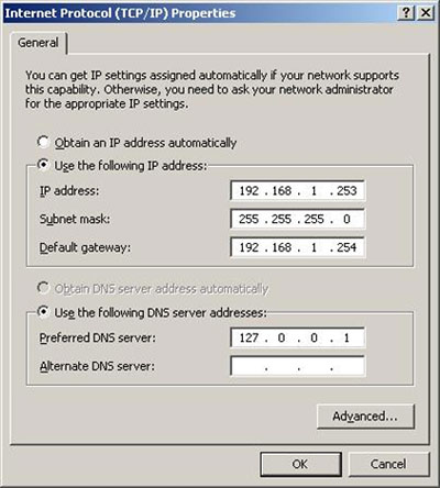
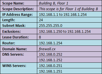
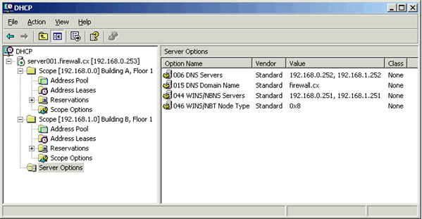
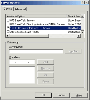
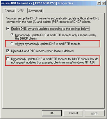
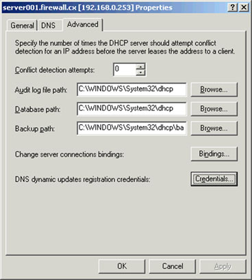
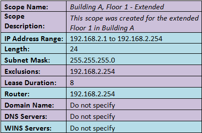
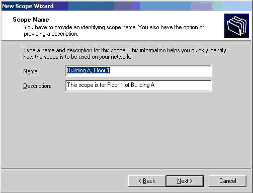
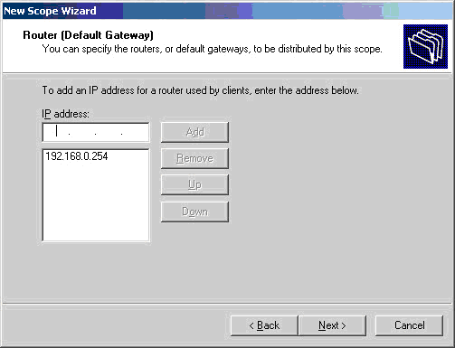
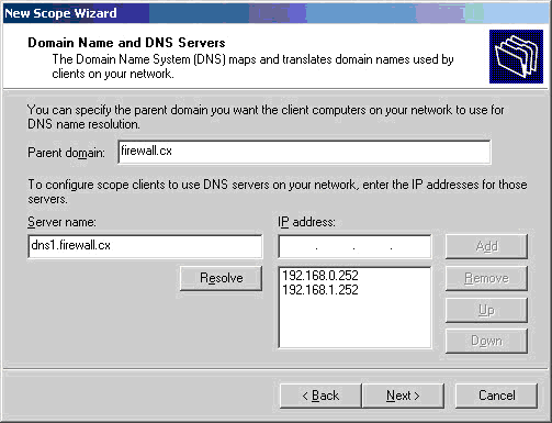
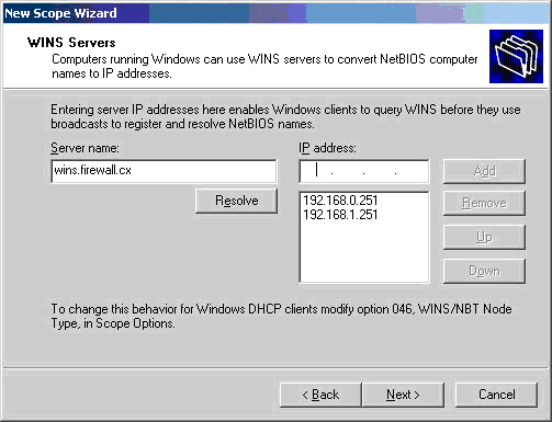
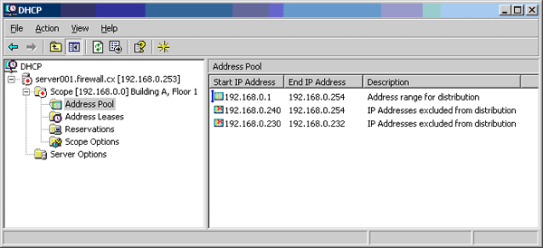
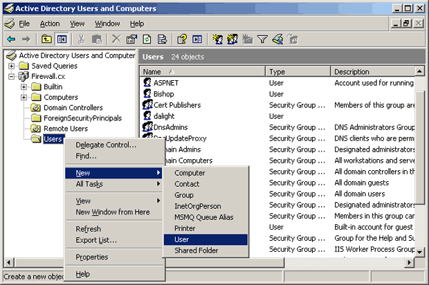
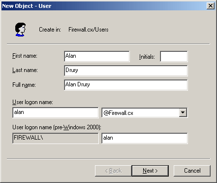
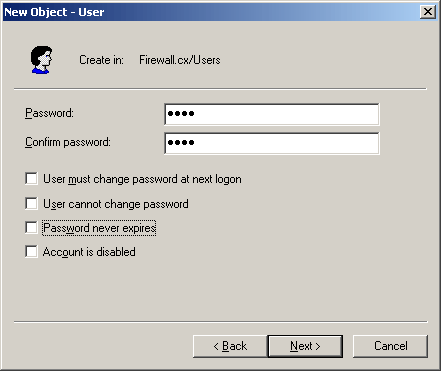
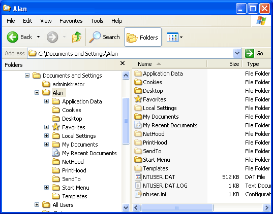
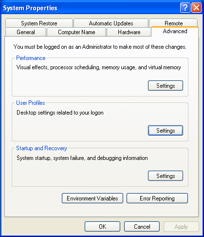
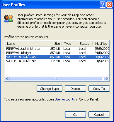
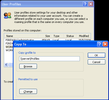
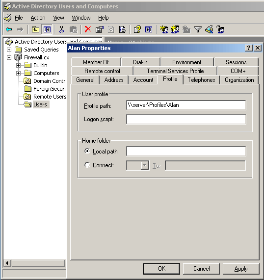
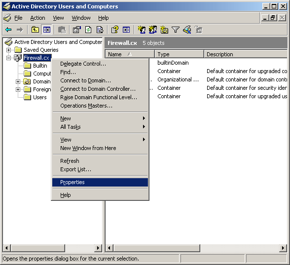
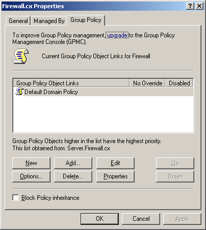
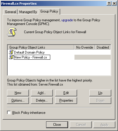
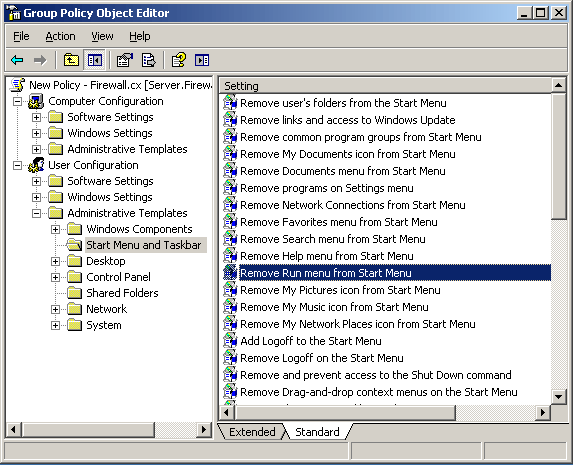


 Windows 8 and Windows 8.1 (including Professional edition) operating systems provide the ability to turn your workstation or laptop into a secure wireless access point, allowing wireless clients (including mobile devices) to connect to the local network or Internet. This feature can save you time, money and frustration when there is need to connect wireless devices to the network or Internet but there is no access point available.


 Figure 5. Network Connections – Ethernet Adapter Properties
 Figure 6. Enabling sharing and selecting the newly created virtual adapter

 Backing up your Windows License Product Key is essential for reinstallation of your Windows 8 or Windows 8.1 operating system. In some cases, the Genuine Microsoft Label or Certificate Of Authenticity (COA) containing the product key, is placed in an area not easily accessible by users e.g inside the battery compartment in newer ultrabooks/laptops, making it difficult to note the product key.
 Figure 2. Running the script reveals our Product Key
 Figure 3. Saving your Windows information to a text file
 Thanks to the absence of dedicated serial ports on today’s laptops and ultrabooks, USB-to-Serial adapters are very popular amongst Cisco engineers as they are used to perform the initial configuration of a variety of Cisco equipment such as routers, catalyst switches, wireless controllers (WLC), access points and more, via their Console Port. The most common USB-to-Serial adapters in the market are based on Profilic’s PL2303 chipset.
 Figure 1. Prolific Adapter in Device Manager
 Figure 2. Prolific Adapter Error Code 10
 Figure 3. Updating the Drivers from Device Manager
 Figure 4. Select Browse my computer for driver software
 Figure 5. Select Let me pick from a list of device drivers on my computer
 Figure 6. Install Driver version 3.3.2.102
 Figure 7. Driver successfully installed
 Figure 8. Fully operational USB-to-Serial adapter
 Figure 1. Creating a New Folder
 Figure 2. Create a new folder & rename it to reveal GodMode
 Figure 3. The GodMode Screen
 Figure 1. Hosts & lmhosts.sam files in File Explorer
 Figure 1. Running CMD as Administrator
 Figure 2. The Administrative Command Prompt Windows 7
 Figure 3. Finding Our Network Adapter ID
 Figure 4. Verifying Our New Network Settings
 Windows 8 & 8.1 hides two types of files so that normally, you do not see them while exploring your computer. The first type is the files or folders with their 'H' attribute set to make them hidden. The other type is Windows System files. The reason behind hiding these files is that users could inadvertently tamper with them or even delete those causing the operations of Windows 8/8.1 to fail. This article explains how you can configure Windows 8 or 8.1 to show all hidden files and folders, plus show Windows system files.
 Figure 1. Icons in the Windows Panel
 Figure 2. File Explorer showing hidden folders and files
 Figure 3. Windows Charms
 Figure 4. Control Panel
 Figure 5. Control Panel - Folder Options
 Figure 6. Folder Options Screen
 This article shows you how to see hiddeen files and folders in Windows 7. Windows 7 hides important system files so that normally, you do not see them while exploring your computer.
 Figure 1. Icons in the Windows Panel
 Figure 2. Organize Menu
 Figure 3. Show hidden files, folders and drives & Hide extensions for known file types
 Figure 4. Start Menu
 Figure 5. Appearance and Personalization screen
 Figure 7. C: Drive showing hidden folders
 Figure 1. Windows 8/8.1 in Safe Mode
 Figure 2. Windows Key +X
 Figure 3. Power User Tasks Menu
 Figure 4. Administrative Command Prompt - Enable F8 Boot Function
 Figure 5. Administrative Command Prompt - Disable F8 Boot Function
 Figure 1. Search Settings
 Figure 2. Advanced Settings Search Result
 Figure 3. PC Settings
 Figure 4. Choose Options
 Figure 5. Troubleshoot Menu
 Figure 6. Advanced Options Menu
 Figure 7. Startup Settings Screen
 Figure 8. Startup Settings Boot Menu
 Figure 1. FW-CL1 IPconfig
 Figure 2. System Settings
 Figure 3. System Properties
 Figure 4. Adding PC to Domain
 Figure 5. Enter Domain Credentials
 Figure 6. Member of Domain
 Not many people are aware that Windows 7 has built-in capabilities that allow it to be transformed into a perfectly working access point so that wireless clients such as laptops, smartphones and others can connect to the local network or obtain Internet access. Turning a Windows 7 system into an access point is an extremely useful feature, especially when there is the need to connect other wireless devices to the Internet with no access point available.


 Security researchers at qualys.com yesterday released information on a critical 15 year-old Linux security hole which affects millions of Linux systems dated back to the year 2000. The newly published security hole – code named ‘Ghost’ was revealed yesterday by Qualy’s security group on openwall.com.


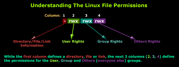
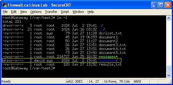
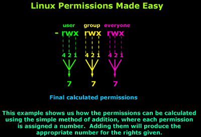

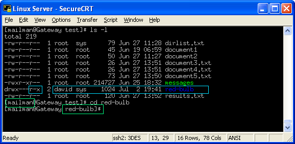
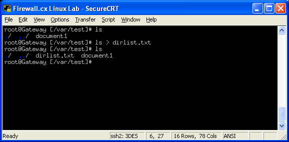
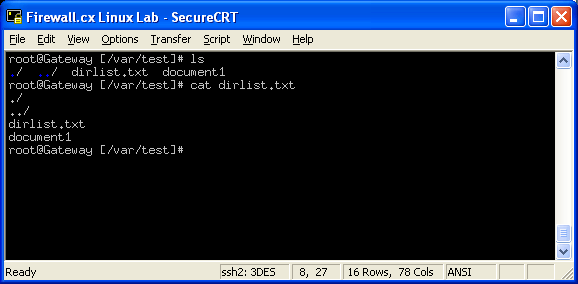
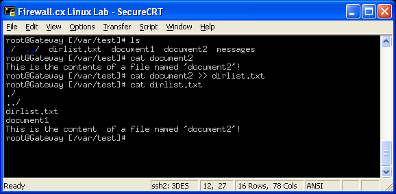
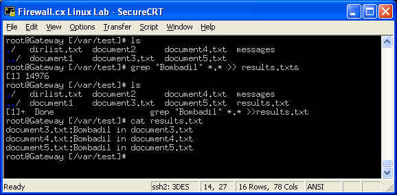
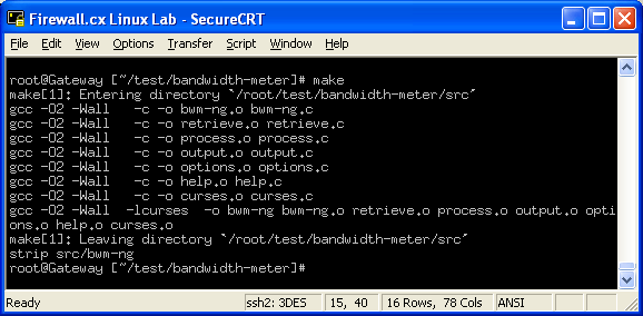
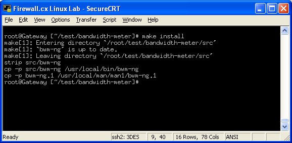
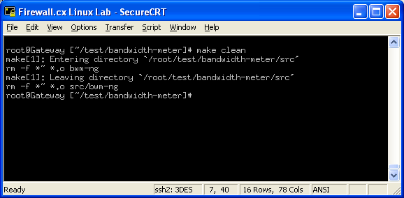
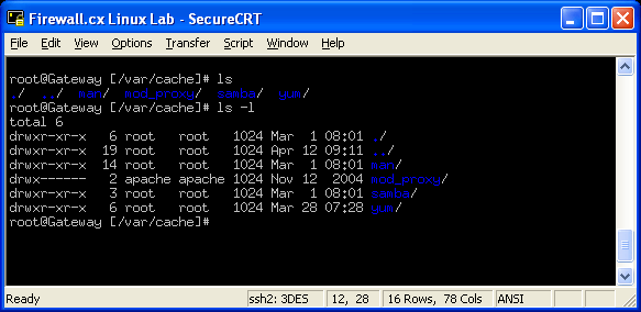

 In this article, we’ll show you how to setup or install Microsoft Windows 11 on VMware’s ESXi servers and bypass the Trusted Platform Module version 2.0 (TPM 2.0) requirement. We've also made the
  Windows 11 Installation Error in VMware ESXi
 Businesses that rely on virtual machines for their day-to-day operations should think twice about securing their infrastructure. Modern use of virtual machines stems from the benefits of virtualization, which include accessibility, reduced operating costs, and flexibility, among others. But your virtual infrastructure becomes obsolete without proper security. One way to achieve that is through virtual machine backup and recovery solutions.
 In this article we will cover the differences between VMware ESXi, vSphere and vCenter while also explain the features supported by each vSphere edition: vSphere Standard, Enterprise plus and Plantium edition. We will touch on the differences and limitations between VMware Workstation Player and VMware Workstation Pro, and also compare them with EXSi Free and EXSi Paid editions.

 You will notice that this vSphere feature table contains many different technologies which are found in different VMware software components.


 VMware Workstation Player and Pro both get installed onto your Windows PC or Laptop, on which you can run your virtual machines. Pro is interesting because you can run as many Virtual Machines as your Windows PC or Laptop hardware can handle making it a great bit of software for running live product demonstrations or testing without needing access to remote infrastructure managed by another team. The key element here is to ensure your laptop or PC has enough resources available (CPU/Cores, RAM and HDD space) for the Virtual Machines that will be running on it.


 SysAdmin Day


 When considering your


 Backup and Disaster recovery are core considerations for any business with an IT footprint, whether that is on-premises or in the cloud.


 In the rapidly evolving landscape of IT operations, organizations are increasingly turning to Artificial Intelligence for IT Operations (AIOps) to streamline their processes, enhance efficiency, and overcome the challenges of managing complex and dynamic IT environments.
 Event noise filtering with the help of AIOps (
 Effective monitoring and management of
 As technology evolves, so do our networks. Today's sprawling network infrastructures are intricate ecosystems, demanding more from IT teams than ever before. Configuration management, compliance enforcement, and firmware & software updates are just a few of the growing requirements that strain manual processes.
 In the rapidly evolving landscape of cyber threats, network security has never been more crucial. With the frequency and sophistication of cyberattacks escalating, organizations are under constant pressure to safeguard their networks. According to Sophos'
 Network alerts are vital for maintaining your network's health, efficiency, and security, ensuring seamless daily operations. They act as an


 Demands for Enterprise networks to properly support mobile users is on a continuous rise making it more than ever necessary for IT departments to provide high-quality services to its users. This article covers 4 key-areas affecting mobile users and Enterprise networks: Wi-Fi coverage (signal strength – signal-to-noise ratio), Bandwidth Monitoring (Wi-Fi Links, Network Backbone, routers, congestion), Shadow IT (Usage of unauthorized apps) and security breaches.


 In today’s evolving threat landscape, firewall audits are more than just a best practice—they're a critical line of defense. Regular audits ensure your firewall configurations are aligned with organizational security policies, eliminate inefficiencies, and reduce exposure to cyber risks. Just as importantly, they help organizations maintain compliance with regulatory standards such as PCI DSS, HIPAA, SOX, and GDPR, avoiding costly penalties and reputational damage. Beyond compliance, effective firewall audits offer operational clarity and control, giving IT and security teams complete visibility into traffic flows and rule configurations.
 A well-maintained and optimized firewall rule base is not just a best practice—it’s a necessity for maintaining a secure, high-performing, and compliant network.


 In today's interconnected digital landscape, where businesses rely heavily on networked systems and the internet for their operations, the importance of cybersecurity cannot be overstated. Among the essential tools in a cybersecurity arsenal, firewalls stand as a frontline defense against cyber threats and malicious actors.
 The utilization of log analyzers, such as

 In the wake of

 This is the process of managing and organizing your firewall rules. These firewall rules and policies dictate the traffic that is entering and exiting your network, and can also be used to block illegitimate traffic.
 This article explores the exciting new features of Windows Server 2022 and emphasizes the critical role of analyzing Windows Server logs. You'll also discover how EventLog Analyzer provides comprehensive, helps you achieve 360-degree protection against threats targeting these logs, ensuring robust security for your server environment.
 Windows Servers
 An event log monitoring system, often referred to as an event log management, is a critical component to IT security & Management, that helps organizations strengthen their cybersecurity posture. It’s a sophisticated software solution designed to capture, analyze, and interpret a vast array of event logs generated by various components within an organization's IT infrastructure such as firewalls (


 This article explains how to detect a SYN Flood Attack using an advanced protocol analyser like Colasoft Capsa. We’ll show you how to identify and inspect abnormal traffic spikes, drill into captured packets and identify evidence of flood attacks. Furthermore we’ll configure Colasoft Capsa to automatically detect SYN Flood Attacks and send automated alert notifications .


 Brute-force attacks are commonly known attack methods by which hackers try to get access to restricted accounts and data using an exhaustive list/database of usernames and passwords. Brute-force attacks can be used, in theory, against almost any encrypted data.


 Colasoft Unified Performance Management (UPM) is a business-oriented network performance management system, which analyzes network performance, quality, fault, and security issues based on business. By providing visual analysis of business performances, Colasoft UPM helps users promote business-oriented proactive network operational capability, ensure the stable running of businesses, and enhance troubleshooting efficiency.


 Peer-to-Peer file sharing traffic has become a very large problem for many organizations as users engage in illegal (most times) file sharing processes that not only consumes valuable bandwidth, but also places the organization in danger as high-risk connections are made from the Internet to the internal network and malware, pirated or copyrighted material or pornography is downloaded into the organization’s systems. The fact is that torrent traffic is responsible for over 29% of US Internet's traffic in North America, indicating how big the problem is.


 Troubleshooting network problems can be a very difficult and challenging task. While most IT engineers use a network analyzer to help solve network problems, when analyzing hundreds or thousands of packets, it can become very hard to locate and further research conversations between hosts. Colasoft’s Capsa v8 now introduces a new feature that allows us to highlight-colorize relevant IP conversations in the network based on their MAC address, IP Addresses, TCP or UDP conversations.


 Figure 1. Selecting our Time-Range, and IP Address of interest from Link Analysis
 Figure 2. nChronos HTTP Reconstruction feature in progress.
 Figure 3. The HTTP Reconstruction process completed
 Troubleshooting network problems can be a very intensive and challenging process. Intermittent network problems are even more difficult to troubleshoot as the problem occurs at random times with a random duration, making it very hard to capture the necessary information, perform troubleshooting, identify and resolve the network problem.


 When working with medium to large scale networks, IT departments are often faced dealing with network loops and


 The developers of the popular software PBX, 3CX, have announced another major update to their unified communications solution! The latest release, 3CX v15.5, makes the phone system faster, more secure and more reliable with a number of improvements and brand new features.
  Web-Client provides leading features packed in an easy-to-use GUI
 IP PBX Web Client with integrated Web Conferencing Free of Charge!
 Click-to-Call Feature from any Web page or CRM

 Crazy as it might sound there is one Unified Communications provider who is giving out free fully functional cloud-based PBX systems without obligation from its users/customers.
 Thanks to its support for any SIP-based IP phone and mobile device (iPhone, Android, iPad, Tablet etc.) the 3CX IP PBX has quickly become the No.1 preferred solution.
 3CX
3CX
 VoIP/ IP PBXs and Unified Communication systems have become extremely popular the past decade and are the No.1 preference when upgrading an existing or installing a new phone system. IP PBXs are based on the IP protocol allowing them to use the existing network infrastructure and deliver enhanced communication services that help organizations collaborate and communicate from anywhere in the world with minimum or no costs.


 Recent and continuous website security breaches on large organizations, federal government agencies, banks and thousands of companies world-wide, has once again verified the importance of website and web application security to prevent hackers from gaining access to sensitive data while keeping corporate websites as safe as possible. Though many encounter a lot of problems when it comes to web application security; it is a pretty heavy filed to dig into.
 Without web hosting services most websites would not exist. The most popular methods to host web applications are:regular hosting, where your web application is hosted on a dedicated server that is intended for your website only, and shared hosting, where you share a web server with other users who will in turn run their own web application on the same server.
 Most successful attacks against web applications are due to insecure code and not the underlying platform itself. Case in point,
  When using software that has been developed by a third party, the best way to ensure that the code is secure would be to apply the latest updates. A simple web application will make use of numerous components that can lead to successful attacks if left unpatched. For example, both PHP and MySQL were vulnerable to exploits at a point in time but were later patched, and a default Linux webserver installation will include multiple services all of which need to be updated regularly to avoid vulnerable builds of software being exploited.
 While updating software will ensure that no known vulnerabilities are present on your system, there may still be entry points where an attacker can access your system that have been missed in our previous tips. This is where firewalls come into play. A firewall is necessary as it will limit traffic depending on your configuration and can also be found on most operating systems by default.
 No amount of code reviews and updates can ensure that the end product is not vulnerable and cannot be exploited. Code reviews are limited since the executed code is not being analysed, which is why web vulnerability scanning is essential. Web scanners will view the web application as a black box, where they will be analysing the finished product, which is not possible with white box scanning or code reviews. Meanwhile, some scanners will also provide you with the option to perform grey box scanning, by combining website scans and a backend agent that can analyse code.
 It is imperative to know if your web application has been subjected to an attack. Monitoring the web application, and the server hosting it, would be the best way to ensure that even if an attacker gets past your defence systems, at least you will know how, when and from where it happened. There may be cases when a website is brought offline due to an attack and the owner would not even know about the incident but will find out after precious time has passed.
 Monitoring, Auditing and obtaining Security Alerts for websites and blogs based on popular CMS systems such as WordPress, has become a necessity. Bugs, security exploits and security holes are being continuously discovered for every WordPress version making monitoring and auditing a high security priority. In addition, multi-user environments are often used for large WordPress websites, making it equally important to monitor WordPress user activity.


 SQL Injections have been keeping security experts busy for over a decade now as they continue to be one of the most common type of attacks against webservers, websites and web application servers. In this article, we explain what a SQL injection is, show you SQL injection examples and analyse how these type of attacks manage to exploit web applications and webservers, providing hackers access to sensitive data.
 A few weeks back Security Weekly interviewed Ferruh Mavituna, Netsparker’s CEO and Product Architect. Security Weekly is a popular podcast that provides free content within the subject matter of IT security news, vulnerabilities, hacking, and research and frequently interviews industry leaders such as John Mcafee, Jack Daniel and Bruce Schneier.
 8th of May 2015, Netsparker annouced yesterday the discovery of critical security vulnerability contained an HTML file found on many WordPress themes, including WordPress.org hosted websites. As reported by Netsparker the specific HTML file is vulnerable to cross-site scripting attacks and session hijack. WordPress.org has already issued an official annoucement and patch (v4.2.2) and recommends WordPress administrators update their website files and themes.
 In the world of information security there exist many tools, from small open source products to full appliances to secure a system, a network, or an entire corporate infrastructure. Of course, everyone is familiar with the concept of a firewall – even movies like Swordfish and TV shows like NCIS have so very perfectly described, in riveting detail, what a firewall is. But there are other, perhaps less sexy utilities in a security paradigm.
 Many websites and web applications are like a human fingerprints, with no two being alike. Of course, many websites may use a common backend engine – Wordpress, an MVC framework like Laravel or Ruby on Rails, etc. – but the layers on top of those engines, such as plugins or custom coded additions, are often a quite unique collection.

 Have you ever tried to make a list of all the attack surfaces you need to secure on your networks and web farms? Try to do it and there will be one thing that will stand out; keeping websites and web applications secure. We have firewalls, IDS and IPS systems that inspect every packet that reaches our servers and are able to drop it should it be flagged as malicious, but what about web applications?
 Many automated security tools exist not to test and find security holes, but to exploit them when found. Black-hat hackers intent on disrupting your web application possess automated suites as well, because they too, know a manual approach is a waste of time (that is, until they find a useful exploit, and by then it’s sometimes too late).
 Netsparker use open source web applications such as Twiki for a total different purpose than what they were intended for. They used them to test their own web application security scanners.
 Long gone are the days where a simple port scan on a company’s webserver or website was considered enough to identify security issues and exploits that needed to be patched. With all the recent attacks on websites and webservers which caused millions of dollars in damage, we thought it would be a great idea to analyze the implications vulnerable webservers and websites have for companies, while providing useful information to help IT Departments, security engineers and application developers proactively avoid unwanted situations.
 In June 2014, JPMorgan Chase bank was hit badly and had sensitive personal and financial data exposed for over 80 million accounts. The hackers appeared to obtain a list of the applications and programs that run on the company’s computers and then crosschecked them with known vulnerabilities for each program and web application in order to find an entry point back into the bank’s systems.
 In January 2014, Snapchat’s popular website had over 4.6 million usernames and phone numbers exposed due to a brute force enumeration attack against their Snapchat API. The information was publicly posted on several other sites, creating a major security concern for Snapchat and its users.
 In 2013 a massive underground attack was uncovered, revealing that over 160 million credit and debit cards were stolen during the past seven years. Five Russians and Ukrainians used advanced hacking techniques to steal the information during these years. Attackers targeted over 800,000 bank accounts and penetrated servers used by the Nasdaq stock exchange.
 This article expands on our popular
 In June 2014, Evernote and Feedly, working largely in tandem, went down with a DDoS attack within two days of each other. Evernote recovered the same day, but Feedly had to suffer more. Although there were two more DDoS attacks on Feedly that caused it to lose business for another two days, normalcy was finally restored. According to the CEO of Feedly, they refused to give in to the demands of ransom in exchange for ending the attack and were successful in neutralizing the threat.
 Domino's Pizza had over 600,000 Belgian and French customer records stolen by the hacking group Rex Mundi. The attackers demanded $40,000 from the fast food chain in exchange for not publishing the data online. It is not clear whether Domino's complied with the ransom demands. However, they reassured their customers that although the attackers did have their names, addresses and phone numbers, they however, were unsuccessful in stealing their financial and banking information. The Twitter account of the hacking group was suspended, and they never released the information.
 Companies and users around the world are struggling to keep their network environments safe from malicious attacks and hijacking attempts by leveraging services provided by high-end firewalls, Intrusion Detection Systems (IDS), antivirus software and other means. While these appliances can mitigate attacks and hacking attempts, we often see the whole security infrastructure failing because of attacks initiated from the inside, effectively by-passing all protection offered by these systems.
 Cybercriminals are now focusing their attention on small and mid-sized businesses because they are typically easier targets than large, multinational corporations.
 This is the age of networks. Long ago, they said, ‘the mainframe is the computer’. Then it changed to ‘the PC is the computer’. That was followed by ‘the network is the computer’. Our world has been shrunk, enlightened and speeded up by this globe encapsulating mesh of interconnectivity. Isolation is a thing of the past. Now my phone brings up my entire music collection residing on my home computer. My car navigates around the city, avoiding traffic in real time. We have started living in intelligent homes where we can control objects within it remotely.
 secure documents were stolen. This resulted in an internal cyber man-hunt. The bait was laid and all further intrusions were monitored. A team of 50 Federal Agents finally tracked down 2 hackers who were using US based social networking systems to hack into the Airforce Base. But it was later revealed that the scope of intrusion was not just limited to the base itself: they had infiltrated a much bigger military organisation. The perpetrators were hackers with the aliases of ‘datastreamcowboy’ and ‘kuji’.
 2005: Miami, Florida. A Miami hacker made history in cyber theft. Alberto Gonzales would drive around Miami streets looking for unsecured wireless networks. He hooked onto the unsecure wireless network of a retailer, used it to reach the retailer’s headquarters and stole credit card numbers from its databases. He then sold these card details to Eastern European cyber criminals. In the first year, he stole 11.2 million card details. By the end of the second year he had stolen about 90 million card details.


 The “Cisco Firepower and Advanced Malware Protection Live Lessons” video series by Omar Santos is the icing on the cake for someone who wants to start their journey of Cisco Next-Generation Network Security. This video series contains eight lessons on the following topics:


 Kevin Wallace is a well-known name in the Cisco industry. Most Cisco engineers and Cisco certification candidates know Kevin from his
  Vivek Tiwari holds a Bachelor’s degree in Physics, MBA and many certifications from multiple vendors including Cisco’s CCIE. With a double CCIE on R&S and SP track under his belt he mentors and coaches other engineers.
 Akhil Behl is a Senior Network Consultant with Cisco Advanced Services, focusing on Cisco Collaboration and Security architectures. He leads Collaboration and Security projects worldwide for Cisco Services and the Collaborative Professional Services (CPS) portfolio for the commercial segment. Prior to his current role, he spent 10 years working in various roles at Linksys, Cisco TAC, and Cisco AS. He holds CCIE (Voice and Security), PMP, ITIL, VMware VCP, and MCP certifications.
 GFI has once again managed to make a difference: They recently published a free eBook named "Cloud-based network monitoring: The new paradigm" as part of their GFI Cloud offerings.
 The screenshot above gives you an idea of what the Server Administration page looks like, which is the first page that would open up once the user has logged in. This is the System Information page. On the left pane you will find several other pages to look at i.e. Basic Settings which displays default port info and HDD info of the host machine, User Account (name says it all), and Audit Log (which will basically show the audit trail of user activity.)
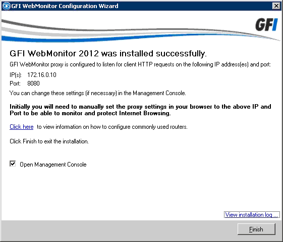
 Many of the displays are clickable allowing you to easily drill down into the data, and if you hover the mouse you’ll get handy pop-up explanations. We were able to go from the overview to the detailed activities of an individual user with just a few clicks. A user here is a single source IP, in other words a particular PC rather that the person using it. Ideally we would have liked the product to query the Active Directory domain controller and nail down the actual logged-on user but to be honest given the reasonable price and the product’s undoubted usefulness we’re not going to quibble.
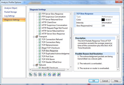
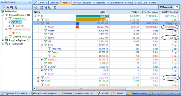
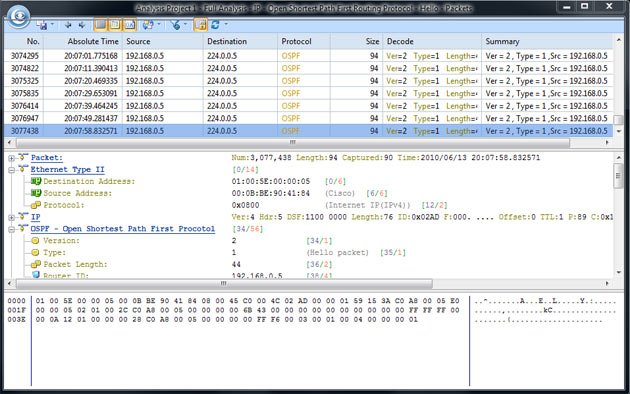
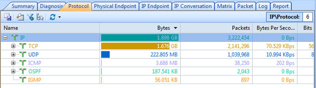
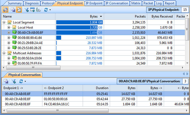
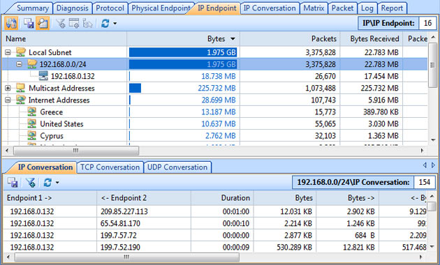
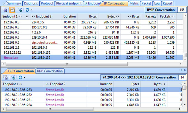
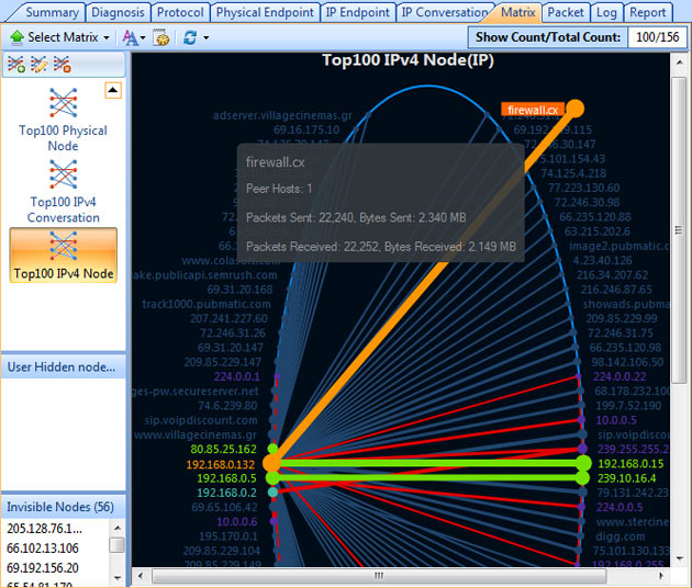
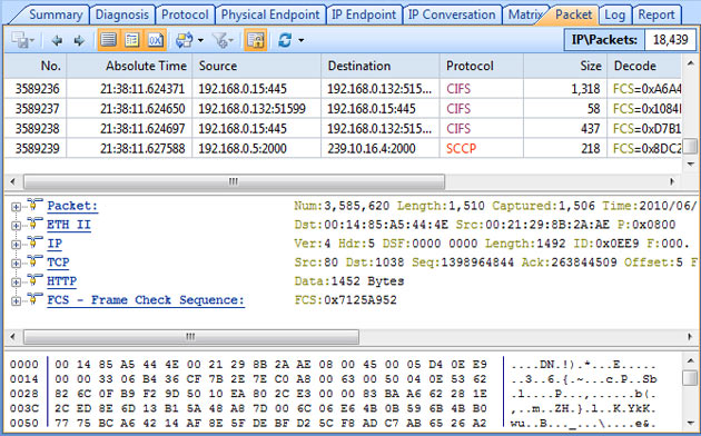
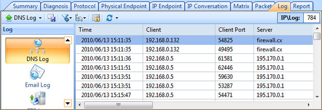
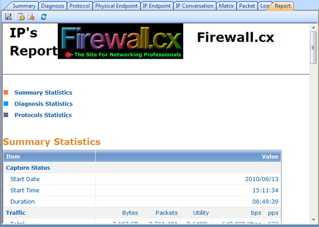


 GFI Software has just revealed GFI OneConnect Beta – its latest Advanced Email Security Protection product. GFI OneConnect is a comprehensive solution that targets the safe and continuous delivery of business emails to organizations around the world.
")
")
 Ensuring users follow company policies when accessing the internet has become a real challenge for businesses and IT staff. The legal implications for businesses not taking measures to enforce acceptable user policies (where possible) can become very complicated and businesses can, in fact, be held liable for damages caused by their users or guests.


 For every business, established or emerging, the Internet is an essential tool which has proved to be indispensable. The usefulness of the internet can be counteracted by abuse of it, by a business’s employees or guests. Activities such as downloading or sharing illegal content, visiting high risk websites and accessing malicious content are serious security risks for any business.


 In this era of constantly pushing for more productivity and greater efficiency, it is essential that every resource devoted to web access within a business is utilised for business benefit. Unless the company concerned is in the business of gaming or social media, etc. it is unwise to use resources like internet/web access, and the infrastructure supporting it, for a purpose other than business. Like they say, “Nothing personal, just business”
")


 In our previous article we analysed the risks and implications involved for businesses when there are no security or restriction policies and systems in place to stop users distributing illegal content (torrents). We also spoke about unauthorized access to company systems, sharing sensitive company information and more. This article talks about how specialized systems such as WebMonitor are capable of helping businesses stop torrent applications accessing the internet, control the websites users access, block remote control software (Teamviewer, Remote Desktop, Ammy Admin etc) and put a stop to users wasting bandwidth, time and company money while at work.
 Senior IT Managers, engineers and administrators surely remember the days where controlling TCP/UDP ports at the Firewall level was enough to block or provide applications access to the internet. For some years now, this is no longer a valid way of application control, as most ‘unwanted’ applications can smartly use common ports such as HTTP (80) or HTTPS (443) to circumvent security policies, passing inspection and freely accessing the internet.
 Apart from the imminent security risk, users who have uncontrollable access are also wasting bandwidth – that’s bandwidth the organization is paying for - and are likely to slow down the internet for the rest who are legitimately trying to get work done. In cases where VPNs are running over the same lines then VPN users, remote branches and mobile users are most likely to experience slow connection speeds when accessing the organization’s resources over the internet.
 One of the largest problems faced by organizations of any size is effectively controlling user internet access (from laptops, mobile devices, workstations etc), minimizing the security threats for the organization (ransomware – data loss prevention), user copyright infringement (torrent downloading/sharing movies, games, music etc) and discover where valuable WAN-Internet bandwidth is being wasted.
 Most Businesses are completely unaware of how serious these matters are and the risks they are taking while dealing with other ‘more important’ matters.
 While illegal downloading is one major threat for businesses, stopping users sharing company data and sensitive information (aka Data Loss Prevention or DLP) is another big problem.
 In late 2015, popular Ammy Admin – a remote control software, was
 Figure 2. GFI LanGuard custom software deployment using a parameter for silent installation


 GFI LanGuard Agents are designed to be deployed on local (network) or remote servers and workstations. Once installed, the GFI LanGuard Agents can then be configured via LanGuard’s main server console, giving the administrator full control as to when the Agents will scan the host they are installed on, and communicate their status to the GFI LanGuard server.


 This article shows how any IT Administrator, network engineer or security auditor can quickly scan a network using GFI’s LanGuard and identify the different systems such as Windows, Linux, Android etc. More importantly, we’ll show how to uncover vulnerable, unpatched or high-risk Windows systems including Windows Server 2003, Windows Server 2008, Windows Server 2012 R2, Domain Controllers, Linux Servers such as RedHat Enterprise, CentOS, Ubuntu, Debian, openSuse, Fedora, any type of Windows workstation (XP, Vista, 7, 8, 8.1,10) and Apple OS X.


 Cisco announced a major update to their CCNA, CCNP and CCIE certification program at Cisco Live last week, with the changes happening on the 24th February 2020.


 So you’ve heard all about Windows Server 2019 - now you can see it in action in a live demo webinar on November 8th! The last WS2019 webinar by Altaro was hugely popular with over 4,500 IT pros registering for the event. Feedback from gathered with that webinar and the most popular features will now be tested live by Microsoft MVP Andy Syrewicze. And you’re invited!

 Downloading all necessary drivers and firmware upgrades for your HP Proliant server is very important, especially if hardware compatibility is critical for new operating system installations or virtualized environments (VMware – HyperV). Til recently, HP customers could download the HP Service Pack (SPP) for Proliant servers free of charge, but that’s no longer the story as HP is forcing customers to pay up in order to get access to its popular SPP package.

 HP SPP ISO is just a click away!")

 Figure 1. Dual firewall configuration
 Broadband access to the Internet by cable modem promises users lightning-fast download speeds and an always-on connection. And recent converts to broadband from dial-up technology are thrilled with complex Web screens that download before their coffee gets cold.

 Firewall.cx’s download section now includes the

 Cisco Lab No.3 - Three high-end Cisco switches flooded in blue lighting, making VLAN services a reality.