VTP Pruning
 VTP (VLAN Trunking Protocol) pruning is a feature that is used in Cisco switches to reduce unnecessary traffic in VLAN (Virtual Local Area Network) trunks. When VTP pruning is enabled on a trunk, the switch will stop forwarding broadcast, multicast, and unknown unicast traffic to VLANs that do not have any active ports.
This feature optimizes network bandwidth utilization by preventing unnecessary traffic from being sent across the network, which can help improve network performance. However, VTP pruning should only be used in situations where there are VLANs with no active ports, as enabling it on all trunks can cause connectivity issues if new ports are added to VLANs in the future.
The Broadcast And Unicast Problem In VLAN Networks
In VLAN (Virtual Local Area Network) networks, broadcast and unicast problems can occur due to the presence of multiple VLANs within a single physical network. Broadcast packets are sent to all hosts on a network, while unicast packets are sent to a specific host. When a broadcast or unicast packet is sent within a VLAN network, it is forwarded to all ports within the same VLAN. If a large number of broadcast or unicast packets are sent, it can lead to network congestion and slow down the overall network performance. To mitigate these issues, VLANs are used to logically separate network traffic, reducing the number of devices that receive unnecessary broadcast and unicast packets. However, proper configuration and management of VLANs are essential to prevent broadcast storms and ensure efficient use of network resources.
The below diagram is an example of how network broadcasts can flood the network, creating uncessary traffic through all trunk links:
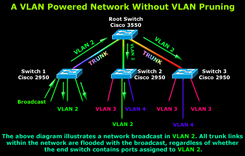
As shown and described, a host connected to a port configured for VLAN 2 on Switch 1 (first switch on the left), generates a network broadcast. Naturally, the switch will forward the broadcast out all ports assigned to the same VLAN it was received from, that is, VLAN 2.
In addition, the Catalyst switch will forward the broadcast out its trunk link, so it may reach all ports in the network assigned to VLAN 2. The Root switch receives the broadcast through one of it's trunks and immediately forwards it to its downlink ports to Switch 2 and Switch 3.
Switch 2 is delighted to receive the broadcast as it does in fact have one port assigned to VLAN 2. Switch 3 however has no ports assigned to VLAN 2 and therefore will drop the broadcast packet received. In this example, Switch 3's uplink received broadcast traffic that was not necessary, therefore wasting valuable bandwidth.
Whie the inefficent usage of Switch 3's uplink doesn't seem like a major issue, the magnitude of this problem can be easily appreciated within a large network of switches as shown in the below diagram:
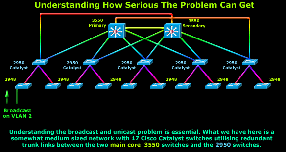
Here we have a medium sized network powered by Cisco Catalyst switches. The two main switches up the top are the VTP servers and also perform Inter-VLAN routing by routing packets between the different VLAN networks.
Below the core switches are the distribution-layer Catalyst switches (2950) with redundant fiber trunk links. Directly below the 2950 switches are the access-layer Catalyst switches (2948) allowing workstations connect to the network.
In this example, a workstation connected to VLAN 2 sends a network broadcast request (lower left corner) to the network. As shown on the diagram, this broadcast will be sent out all network ports assigned to VLAN 2 on the local switch, but also out through all uplink ports to other switches. The same will occur on all other switches, causing a large amount of uncessary traffic through network uplinks:
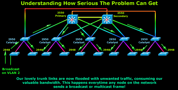
We can appreciate how much uncessary traffic is generated here and how easily switch uplinks can be flooding with broadcast traffic.
Once can still argue that in today's modern multi-gigabit networks, this would be insignificant traffic, however from a design perspective, this is by far not an efficient network design.
The Solution: Enabling VTP Pruning
VTP Pruning as you might have already guessed solves the above problem by reducing the unnecessary flooded traffic described previously. This is done by forwarding broadcasts and unknown unicast frames on a VLAN over trunk links only if the switch on the other end of the link has ports configured for that VLAN.
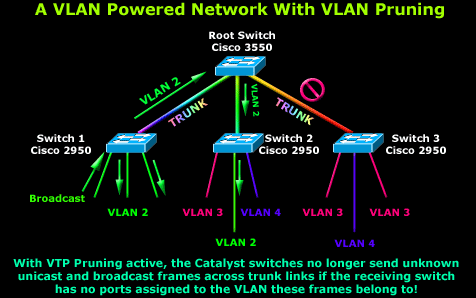
Looking at the above diagram you will notice that the Root Catalyst 3550 Switch receives a broadcast from Switch 1, but only forwards it out one of it's trunks. The Root Switch knows that the broadcast belongs to VLAN 2 and furthermore it's aware no port is assigned to VLAN 2 on Switch 3, therefore it won't forward it out the trunk link connecting to that switch.
Support For VTP Pruning
The VTP Pruning service is supported by both VTP 1 and VTP 2 versions of the VTP protocol. With VTP 1, VTP pruning is possible with the use of additional VTP message types.
When a Cisco Catalyst switch has ports associated with a VLAN, it will send an advertisement to its neighboring switches informing them about the ports it has active on that VLAN. This information is then stored by the neighbors and used to decide if flooded traffic from a VLAN should be forwarded to the switch via the trunk port or not.
VTP Pruning configuration and commands are covered in section 11.4 as outlined in the VLAN Introduction page, however, we should inform you that you can actually enable pruning for specific VLANs in your network.
When you enable VTP Pruning on your network, all VLANs become eligible for pruning on all trunk links. This default list of pruning eligibility can thankfully be modified to suite your needs but you must first clear all VLANs from the list using the clear vtp prune-eligible vlan-range command and then set the VLAN range you wish to add in the prune eligible list by issuing the following command: set vtp prune-eligible vlan-range where the 'vlan-range' is the actual inclusive range of VLANs e.g '2-20'.
By default, VLANs 2–1000 are eligible for pruning. VLAN 1 has a special meaning because it is normally used as a management VLAN and is never eligible for pruning, while VLANs 1001–1005 are also never eligible for pruning. If the VLANs are configured as pruning-ineligible, the flooding continues as illustrated in our examples.
VTP Pruning is disabled by default on all Cisco Catalyst switches and can be enabled by issuing the set vtp pruning enable command on the VTP Server. This will also enable VTP pruning for the entire management domain.
Summary
VTP Pruning is a much welcomed feature within any VTP-enabled Cisco powered network, assiting in increasing bandwidth availability by restricting broadcast and unknown unicast traffic. We provided examples on how VTP can be configured and the effects it has in a small but also large network.
Wi-Fi Key Generator
Follow Firewall.cx
Cisco Password Crack
Decrypt Cisco Type-7 Passwords on the fly!


