


Cisco Aironet Access Points, just like most Cisco devices, provide a web interface from which we are able to configure the device. It is often we are presented with a number of options and settings, which we really are not sure why they exist, what they do, and how they can affect the performance of our wireless access point. This is all about to change!
This article aims to help cover this gap by explaining the various configuration options and settings found in Cisco's Aironet series Web-Based configuration page. While the web-based interface allows the configuration of many functions within the Aironet device, we will be focusing on the 'Network Interfaces: Radio0-802.11a/b/g' Settings, which is perhaps the most important section for the device's proper wireless operation.
Understanding and configuring correctly your Cisco Aironet Access Points can really make a difference in your clients wireless performance and connectivity range. You'd be suprised on the performance difference of your wireless network, when tweaking your Cisco Aironet Access Points to adapt to the working environment.
This article explains all the network options found under the Cisco Aironet web-interface setup, in a step-by-step manner. To help make it easier to track, we have broken the page into three sections, each containing a screenshot of the covered options.
Please note that some features and settings will not appear on your Cisco Aironet Access Point as they are supported only on specific models:
Cisco Aironet Network Interfaces: Radio0-802.11a/b/g Settings
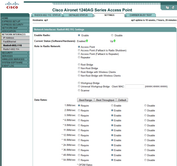
Enable Radio
If enabled, the access point sends packets through its 802.11a/b/g radio interface and monitors when other devices use the 802.11a/b/g radio interface to send packets. To change the administrative state of the radio from up to down, choose Disable. To change the administrative state of the radio from down to up, choose Enable.
Current Status (Software/Hardware)
-
Software - Indicates whether the interface has been enabled or disabled by the user.
- Hardware - Indicates whether the line protocol for the interface is up or down.
Role in Radio Network
Select the role of the access point on your network. Choose one of the three access point (root) settings if the access point is connected to the wired LAN.
Access Point Root (Fallback to Radio Island): This default setting enables wireless clients to continue to associate even when there is no connection to the wired LAN.
Access Point Root (Fallback to Repeater): When the wired connection is lost, the radio becomes a repeater. The repeater parent should be configured to allow data to be wirelessly transferred to another access point.
Repeater Non-Root: Choose this setting if the access point is not connected to the wired LAN. Client data is transferred to the access point selected as the repeater parent. The repeater parent may be configured as an access point or another repeater.
Fallback Mode Upon Loss of Ethernet Connection: Access points operate as root access points by default. When set to defaults, Cisco Aironet 1400 Series Wireless Bridges start up in install mode and adopt the root role if they do not associate to another bridge. If a 1400 series bridge associates to another bridge at start-up, it automatically adopts the non-root role. Cisco Aironet 1300 Series Wireless Bridges operate as root bridges by default.
Repeater: Specifies that the access point is configured for repeater operation. Repeater operation indicates the access point is not connected to a wired LAN and must associate to a root access point that is connected to the wired LAN.
Root: On access points, specifies that the access point is configured for root mode operation and connected to a wired LAN. This parameter also specifies that the access point should attempt to continue access point operation when the primary Ethernet interface is not functional.
Root Bridge: On 1300 series bridges, specifies that the bridge functions as a root access point. If the Ethernet interface is not functional, the unit attempts to continue access point operation. However, you can specify a fallback mode for the radio. This option is supported only on 1300 series bridges.
Non-root Bridge: On 1400 series bridges, specifies that the bridge operates as a non-root bridge and must associate to a root bridge. This option is supported only on 1400 series bridges.
Fallback Shutdown (Optional): Specifies that the access point should shutdown when the primary Ethernet interface is not functional. This option is supported only on access points and on 1300 series bridges in access point mode.
Fallback Repeater (Optional): Specifies that the access point should operate in repeater mode when the primary Ethernet interface is not functional. This option is supported only on access points and on 1300 series bridges in access point mode.
Install: On 1400 series bridges, configures the bridge for installation mode. In installation mode, the bridge flashes its LEDs to indicate received signal strength (RSSI) to assist in antenna alignment. This option is supported only on 1400 series bridges.
Workgroup-Bridge: On 1300 series bridges, specifies that the bridge operates in workgroup bridge mode. As a workgroup bridge, the device associates to an access point or bridge as a client and provides a wireless LAN connection for devices connected to its Ethernet port. This option is supported only on 1300 series bridges.
Universal Workgroup Bridge Mode: When configuring the universal workgroup bridge roll, you must include the client's MAC address. The workgroup bridge will associate with this MAC address only if it is present in the bridge table and is not a static entry. If validation fails, the workgroup bridge associates with its BVI's MAC address. In universal workgroup bridge mode, the workgroup bridge uses the Ethernet client's MAC address to associate with Cisco or non-Cisco root devices. The universal workgroup bridge is transparent and is not managed.
Scanner: This option is supported only when used with a WLSE device on your network. It specifies that the access point operates as a radio scanner only and does not accept associations from client devices. As a scanner, the access point collects radio data and sends it to the WDS access point on your network. This option is supported only on access points.
Data Rates
Use the data rates setting to choose the data transmission rates. The rates are expressed in megabits per second. The device always attempts to transmit at the highest rate selected. If there are obstacles or interference, the device steps down to the highest rate that enables data transmission.
Click the Best Range button to optimize access point range or the Best Throughput button to optimize throughput.
Note: When you configure the 802.11g access point radio for best throughput, the access point sets all 802.11g data rates to basic (required). This setting blocks association from 802.11b client devices.
For each of the rates, choose Require, Enable, or Disable.
-
Require - Enables transmission at this rate for all packets, both unicast and multicast. At least one data rate must be set to Require. A client must support a required rate before it can associate.
-
Enable - Enables transmission at this rate for unicast packets only.
-
Disable - Does not allow transmission at this rate.
Note: The client must support the basic rate you select or it cannot associate with the access point.
![]()
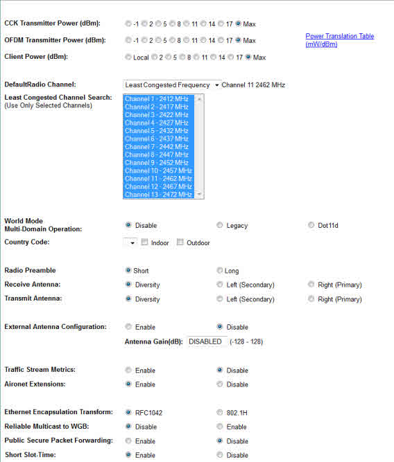
Transmit Power: This setting determines the power level of the radio transmission. The default power setting is the highest transmit power allowed in your regulatory domain.
Note: Government regulations define the highest allowable power level for radio devices. This setting must conform to established standards for the country in which you use the device.
To reduce interference, limit the range of your access point, or to conserve power, select a lower power setting.
For an 802.11g radio, Transmit Power is divided into CCK Transmit Power and OFDM Transmit power. CCK is the modulation used in 802.11g for the lower frequency rates, and OFDM is the modulation used in 802.11g for higher data rates (above 20 Mbps).
Note: The 100 mW (20dBM) value is not available for rates greater than 12 Mbps.
Power Translation Table (mW/dBm)
The power settings may be in mW or in dBm depending on the particular radio that is being configured. This table translates between mW and dBm.
Limit Client Power (mw): Determine the maximum power level allowed on client devices that associate to the access point. When a client device associates to the access point, the access point sends the maximum power level setting to the client.
Note: The 100 mW value is not available for rates greater than 12 Mbps.
Default Radio Channel: The available selection of radio channels is determined by your regulatory domain. The default setting is the least-congested frequency. With this setting, the device scans for the radio channel that is least busy and selects that channel for use. The device scans at power-up and when the radio settings are changed. You can also select specific channel settings from the Default Radio Channel drop-down menu.
Short Slot Time (for 802.11g radios only): Determine if you want to enable support for the Extended-Rate-PHY short slot time. Enabling this setting reduces the slot time from the standard 20 microseconds to 9 microseconds to increase throughput.
Least Congested Channel Search: This selection list is available only when Default Radio Channel is set to Least Congested Frequency. You can search for least congested channels but exclude some channel(s) which are known to be problematic or already in use by other applications. By default, all channels are selected and searched. To select more than one channel, hold down the Ctrl or Shift keys to highlight multiple channels.
World Mode Multi-Domain Operation (for 802.11b and 802.11g only): World mode operation is disabled by default. If you uncheck Disable, the device adds channel carrier set information to its beacon. Client devices with world-mode enabled receive the carrier set information and adjust their settings automatically. If you select the dot11d option, you must enter an ISO country code. If you select the legacy option, you enable Cisco legacy world mode.
With world mode enabled, the access point advertises the local settings, such as allowed frequencies and transmitter power levels. Clients with this capability then passively detect and adopt the advertised world settings, and then actively scan for the best access point.
Country Code (required only for dot11d option): A country code can be selected only if the dot11d option was chosen in the World Mode option above. Use the drop-down menu to select the appropriate country. After the country code, you must enter indoor or outdoor to indicate the placement of the access point.
Radio Preamble (802.11b and 802.11g only): The radio preamble is a section of data at the head of a packet that contains information the access point and the client devices need when sending and receiving packets. Keep the setting on short unless you want to test with long preambles. If you have the radio preamble set to short and a client associates that does not support short preamble associates, the access point will send only long preamble packets to this client.
-
Short - A short preamble improves throughput performance. Cisco Aironet's Wireless LAN Adapter supports short preambles. The access point and client negotiate the use of the short preamble. Early models of Cisco Aironet's Wireless LAN Adapter require long preambles.
-
Long - A long preamble ensures compatibility between the access point and all early models of Cisco Aironet Wireless LAN Adapters.
Receive Antenna and Transmit Antenna:
-
Diversity - This default setting tells the device to use the antenna that receives the best signal. If your device has two fixed (non-removable) antennas, you should use this setting for both receive and transmit.
-
Left (secondary)- If your device has removable antennas and you install a high-gain antenna on the left connector, you should use this setting for both receive and transmit. When you look at the back panel, the left antenna is on the left.
-
Right (primary)- If your device has removable antennas and you install a high-gain antenna on the right connector, you should use this setting for both receive and transmit. When you look at the back panel, the right antenna is on the right.
Note: The device receives and transmits using only one antenna at a time, so you cannot increase range by installing high-gain antennas on both connectors and pointing one north and one south. When the device uses the north-pointing antenna, client devices to the south should be ignored by the access point.
External Antenna Configuration: This feature is currently not operational, but it may be supported in future releases.
Antenna Gain(dB): The gain of an antenna is a measure of the antenna's ability to direct or focus radio energy over a region of space. High-gain antennas have a more focused radiation pattern in a specific direction. This setting is disabled on the bridge.
Aironet Extensions: Select Enable to use Cisco Aironet 802.11 extensions. This setting must be set to Enable so that you can use load balancing, MIC, and TKIP.
Ethernet Encapsulation Transform: Choose 802.1h or RFC1042to set Ethernet encapsulation type. Data packets that are not 802.2 packets must be formatted to 802.2 with 802.1h or RFC1042. Cisco Aironet equipment defaults to RFC1042 because it provides optimum interoperability.
-
802.1h - This setting provides optimum performance for Cisco Aironet wireless products.
-
RFC1042 - Use this setting to ensure interoperability with non-Cisco Aironet wireless equipment. RFC1042 does not provide the interoperability advantages of 802.1h but is used by other manufacturers of wireless equipment.
Reliable Multicast to WGB: Normally, an access point treats a workgroup bridge as an infrastructure device and not as a client. The access point uses the reliable multicast protocol to ensure delivery of all multicast packets. The extra traffic caused by reliable delivery limits the number of workgroup bridges that can be associated. Select Disableto allow the workgroup bridge to be treated as a non-infrastructure device and thus allow the maximum number of workgroup bridges to be associated.
Public Secure Packet Forwarding: Public Secure Packet Forwarding (PSPF) prevents client devices associated to an access point from inadvertently sharing files or communicating with other client devices associated to the access point. It provides Internet access to client devices without providing other capabilities of a LAN.
No exchange of unicast, broadcast, or multicast traffic occurs between protected ports. Choose Enable so that the protected port can be used for secure mode configuration.
PSPF must be set per VLAN.
Note: To prevent communication between clients associated to different access points on your wireless LAN, you must set up protected ports on the switch to which your access points are connected.
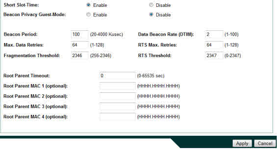
Short Slot Time: You can increase throughput on the 802.11g radio by enabling short slot time. Reducing the slot time from the standard 20 microseconds to the 9-microsecond short slot time decreases the overall backoff time, which increases throughput. Backoff time, which is a multiple of the slot time, is the random length of time that a station waits before sending a packet on the LAN.
When you enable short slot time, the access point/bridge uses the short slot time only when all clients associated to the 802.11g radio support short slot time. Short slot time is disabled by default.
Beacon Privacy Guest-Mode: This command must be configured if you wish the beacon frames to use the privacy settings of the guest-mode SSID. If there is no guest-mode SSID configured, the command has no effect. If there is a guest-mode SSID and the command is configured, the privacy bit present in the beacon frames are set to ON/OFF according to how the security (encryption) settings of the guest-mode SSID are configured.
The command has no effect in MBSSID mode.
Beacon Period: The beacon period is the amount of time between access point/bridge beacons in kilomicroseconds. One Kusec equals 1,024 microseconds. The default beacon period is 100
Data Beacon Rate (DTIM): This setting, always a multiple of the beacon period, determines how often the beacon contains a delivery traffic indication message (DTIM). A traffic indication map is present in every beacon. The DTIM notifies power-save client devices that a packet is waiting for them. If power save clients are active, the access point buffers any multicast traffics and delivers them immediately after the DTIM beacon. Power save nodes always wake for the DTIM beacons. The longer the time, the more buffering the access point does, and the longer the multicasts are delayed.
If the beacon period is set at 100 (its default setting), and the data beacon rate is set at 2 (its default setting), then the device sends a beacon containing a DTIM every 200 Kusec. One Kusec equals 1,024 microseconds.
Max. Data Retries: The maximum number of attempts the device makes to send a packet before giving up, dropping the packet, and disassociating the client.
RTS Max. Retries: The maximum number of times the device issues an RTS before stopping the attempt to send the packet through the radio. Enter a value from 1 to 128.
Fragmentation Threshold: This setting determines the size at which packets are fragmented (sent as several pieces instead of as one block). Use a low setting in areas where communication is poor or where there is a great deal of radio interference.
RTS Threshold: This setting determines the packet size at which the device issues a request to send (RTS) before sending the packet. A low RTS Threshold setting can be useful in areas where many client devices are associating with the access point or in areas where the clients are far apart and can detect only the access point and not each other.
Repeater Parent AP Timeout: If this timeout is enabled, the access point in repeater mode looks only for the parent access point specified in the following Repeater Parent AP MAC definition for this given amount of time. If the timeout expires, the list is ignored, and the unit associates to an access point that matches its requirements, regardless of its MAC address. If the timeout is disabled, the repeater associates only to parents in the list and continues the search.
Repeater Parent AP MAC 1-4: Normally, a repeater access point (without a wired LAN connection) associates much like a normal client, choosing the best access point it can find. Enter MAC addresses in this list if you want to control the parent access point to which a repeater may associate. If MAC addresses are entered in this list, a repeater associates only to a parent whose MAC address matches an entry in the list. If the first MAC address is not available, the access point continues through the list and waits the amount of time specified in Repeater Parent AP Timeout field before trying the next.
Free eBook - Endpoint Security

Enterprise-Class Cloud & Network Monitoring

Bandwidth Monitor

Wi-Fi Key Generator
Network and Server Monitoring

Follow Firewall.cx
Recommended Downloads
Cisco Password Crack
Decrypt Cisco Type-7 Passwords on the fly!
Automated Patching Solution

Firewall Analyzer
