


Site-to-Site IPSec VPN Tunnels are used to allow the secure transmission of data, voice and video between two sites (e.g offices or branches). The VPN tunnel is created over the Internet public network and encrypted using a number of advanced encryption algorithms to provide confidentiality of the data transmitted between the two sites.
This article will show how to setup and configure two Cisco routers to create a permanent secure site-to-site VPN tunnel over the Internet, using the IP Security (IPSec) protocol. In this article we assume both Cisco routers have a static public IP address. Readers interested in configuring support for dynamic public IP address endpoint routers can refer to our Configuring Site to Site IPSec VPN with Dynamic IP Endpoint Cisco Routers article.
IPSec VPN tunnels can also be configured using GRE (Generic Routing Encapsulation) Tunnels with IPsec. GRE tunnels greatly simply the configuration and administration of VPN tunnels and are covered in our Configuring Point-to-Point GRE VPN Tunnels article. Lastly, DMVPNs – a new VPN trend that provide major flexibility and almost no administration overhead can also be examined by reading our Understanding Cisco Dynamic Multipoint VPN (DMVPN), Dynamic Multipoint VPN (DMVPN) Deployment Models & Architectures and Configuring Cisco Dynamic Multipoint VPN (DMVPN) - Hub, Spokes , mGRE Protection and Routing - DMVPN Configuration articles.
ISAKMP (Internet Security Association and Key Management Protocol) and IPSec are essential to building and encrypting the VPN tunnel. ISAKMP, also called IKE (Internet Key Exchange), is the negotiation protocol that allows two hosts to agree on how to build an IPsec security association. ISAKMP negotiation consists of two phases: Phase 1 and Phase 2.
Phase 1 creates the first tunnel, which protects later ISAKMP negotiation messages. Phase 2 creates the tunnel that protects data. IPSec then comes into play to encrypt the data using encryption algorithms and provides authentication, encryption and anti-replay services.
IPSec VPN Requirements
To help make this an easy-to-follow exercise, we have split it into two steps that are required to get the Site-to-Site IPSec VPN Tunnel to work.
These steps are:
(1) Configure ISAKMP (ISAKMP Phase 1)
(2) Configure IPSec (ISAKMP Phase 2, ACLs, Crypto MAP)
Our example setup is between two branches of a small company, these are Site 1 and Site 2. Both the branch routers connect to the Internet and have a static IP Address assigned by their ISP as shown on the diagram:
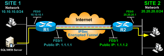
Site 1 is configured with an internal network of 10.10.10.0/24, while Site 2 is configured with network 20.20.20.0/24. The goal is to securely connect both LAN networks and allow full communication between them, without any restrictions.
Configure ISAKMP (IKE) - (ISAKMP Phase 1)
IKE exists only to establish SAs (Security Association) for IPsec. Before it can do this, IKE must negotiate an SA (an ISAKMP SA) relationship with the peer.
To begin, we’ll start working on the Site 1 router (R1).
First step is to configure an ISAKMP Phase 1 policy:
The above commands define the following (in listed order):
We should note that ISAKMP Phase 1 policy is defined globally. This means that if we have five different remote sites and configured five different ISAKMP Phase 1 policies (one for each remote router), when our router tries to negotiate a VPN tunnel with each site it will send all five policies and use the first match that is accepted by both ends.
Next we are going to define a pre shared key for authentication with our peer (R2 router) by using the following command:
The peer’s pre shared key is set to firewallcx and its public IP Address is 1.1.1.2. Every time R1 tries to establish a VPN tunnel with R2 (1.1.1.2), this pre shared key will be used.
Configure IPSec - 4 Simple Steps
To configure IPSec we need to setup the following in order:
- Create extended ACL
- Create IPSec Transform
- Create Crypto Map
- Apply crypto map to the public interface
Let us examine each of the above steps.
Step 1: Creating Extended ACL
Next step is to create an access-list and define the traffic we would like the router to pass through the VPN tunnel. In this example, it would be traffic from one network to the other, 10.10.10.0/24 to 20.20.20.0/24. Access-lists that define VPN traffic are sometimes called crypto access-list or interesting traffic access-list.
R1(config-ext-nacl)# permit ip 10.10.10.0 0.0.0.255 20.20.20.0 0.0.0.255
Step 2: Create IPSec Transform (ISAKMP Phase 2 policy)
Next step is to create the transform set used to protect our data. We’ve named this TS:
The above command defines the following:
Step 3: Create Crypto Map
The Crypto map is the last step of our setup and connects the previously defined ISAKMP and IPSec configuration together:
We’ve named our crypto map CMAP. The ipsec-isakmp tag tells the router that this crypto map is an IPsec crypto map. Although there is only one peer declared in this crypto map (1.1.1.2), it is possible to have multiple peers within a given crypto map.
Step 4: Apply Crypto Map To The Public Interface
The final step is to apply the crypto map to the outgoing interface of the router. Here, the outgoing interface is FastEthernet 0/1.
R1(config- if)# crypto map CMAP
Note that you can assign only one crypto map to an interface.
As soon as we apply crypto map on the interface, we receive a message from the router that confirms isakmp is on: “ISAKMP is ON”.
At this point, we have completed the IPSec VPN configuration on the Site 1 router.
We now move to the Site 2 router to complete the VPN configuration. The settings for Router 2 are identical, with the only difference being the peer IP Addresses and access lists:
Network Address Translation (NAT) and IPSec VPN Tunnels
Network Address Translation (NAT) is most likely to be configured to provide Internet access to internal hosts. When configuring a Site-to-Site VPN tunnel, it is imperative to instruct the router not to perform NAT (deny NAT) on packets destined to the remote VPN network(s).
This is easily done by inserting a deny statement at the beginning of the NAT access lists as shown below:
For Site 1’s router:
And Site 2’s router:
Establishing and Verifying the IPSec VPN Tunnel
At this point, we’ve completed our configuration and the VPN Tunnel is ready to be brought up. To initiate the VPN Tunnel, we need to force one packet to traverse the VPN and this can be achieved by pinging from one router to another:
The first icmp echo (ping) received a timeout, but the rest received a reply, as expected. The time required to bring up the VPN Tunnel is sometimes slightly more than 2 seconds, causing the first ping to timeout.
To verify the VPN Tunnel, use the show crypto session command:
Summary
This completes our discussion on how to setup and configure two Cisco routers to create a permanent secure site-to-site VPN tunnel over the Internet, using the IP Security (IPSec) protocol.
All-in-one protection for Microsoft 365

FREE Hyper-V & VMware Backup

Enterprise-Class Cloud & Network Monitoring

Wi-Fi Key Generator
Network and Server Monitoring

Follow Firewall.cx
Recommended Downloads
Cisco Password Crack
Decrypt Cisco Type-7 Passwords on the fly!
Bandwidth Monitor

Free PatchManager

Security Podcast

Firewall Analyzer
