
 This article will show you how to configure an IPSec VPN tunnel between a Palo Alto firewall (all PANOS versions) and Meraki MX security appliance. Our comprehensive guide includes IPSec VPN setup for static & dynamic IP endpoints, Full tunnel VPN configuration, Split tunnel VPN configuration, special considerations for Full & Split tunnel modes, IPSec Phase 1 - IKE gateway & crypto policies, IPSec Phase 2 – Tunnel encryption algorithms & authentication plus more.
Key Topics:
Palo Alto Firewall Setup
- Step 1 – Create a Tunnel Interface
- Step 2 – Configure IKE Crypto Profile (IKEv1 - Phase 1)
- Step 3 – Configure IKE Gateway
- Step 4 – Configure IPSec Crypto Profile – (IKE Phase 2)
- Step 5 – Create IPSec Tunnel
- Step 6 – Configure VPN Routing (Remote Site Traffic)
- Step 7 – Configure Security Policies (IKE/IPSec & Remote Site Traffic)
Meraki MX Security Appliance Setup
- Step 1 – Enable Site-to-Site VPN
- Step 2 – Enable VPN Mode for Local Networks
- Step 3 – Configure Non-Meraki VPN Peer, IKE Version, Auth ID, Subnets & Preshared Secret
- Step 4 – Configure IPSec Policies (Phase 1 & Phase 2)
- Step 5 – Split Tunnel and Full Tunnel Mode
- Step 6 - Initiate and Test the VPN Tunnel
- Summary
This article assumes both Palo Alto firewall and Meraki MX are fully configured to allow local clients access to the internet. We’ll first begin with the configuration of the Palo Alto firewall and then work on the Meraki MX appliance.
Visit our Palo Alto Firewall section for more articles covering Palo Alto technologies.
Step 1 – Create a Tunnel Interface
Under Network, select Interfaces then the Tunnel menu option. The firewall will now show all configured tunnel interfaces. The interface ‘tunnel’, as shown below, by default exists on all firewalls:

Finally, Click on Add to create and configure the new tunnel interface. The Virtual Router and Security Zone are the bare minimum that need to be configured:

Note: Configuring an IP address (IPv4) on the tunnel interface is required only if you intend to run dynamic routing protocols over the tunnel interface.

 Creating a Tunnel interface and assigning a MGT profile - Click to enlarge
Step 2 – Configure IKE Crypto Profile (IKEv1 - Phase 1)
 Creating an IKE crypto profile - Click to enlarge
We can now define the IKE Crypto profile parameters. In the popup window, enter the name for the IKE profile and select a compatible DH Group, Authentication and Encryption method. Our setup shows the most secure options (DH Group, Authentication, Encryption) currently supported by our Meraki MX appliance:

- DH Group: group14 (2048-bit)
- Authentication: sha256
- Encryption: aes-256-cbc
- Key Lifetime: 4 hours (8 hours is the default value)
Step 3 – Configure IKE Gateway
Next step is to configure the IKE Gateway. Select Network, Network Profiles and finally IKE Gateways. When ready, click on the Add button:
 Creating an IKE Gateway on a Palo Alto firewall - Click to enlarge
The IKE Gateway window contains a number of different parameters that need to be populated:
 Configuring an IKE Gateway - General Options - on a Palo Alto firewall - Click to enlarge
Below are a few options that require special consideration:
- Version: The IKE version must be identical with the remote peer. Supported options are IKEv1, IKEv2 and IKEv2 preferred mode. With IKEv2 preferred mode, the firewall will attempt to negotiate IKEv2 but will fail back to IKEv1 if it’s not supported.
- Interface: This is the public facing interface. Select a Physical or Aggregate interface (AE).
- Local IP Address: This is the IP address for the interface where the tunnel terminates. Option None can be used if the Palo Alto firewall has a dynamic public IP (like our case) or only a single static IP. Alternatively you can specify the public IP to be used.
- Peer IP Address Type: Static IP is the most secure, followed by FQDN and finally Dynamic. With the Dynamic option, the peer always initiates the IKE gateway negotiation. If the peer is subject to dynamic IP address changes, it’s recommended to use FQDN (hostname) or FQDN (email address) for the Peer Identification (see below).
- Authentication: The type of authentication that will occur with the peer gateway.
- Local Identification: Format and identification of the local VPN gateway used with the pre-shared key for both IKEv1 Phase 1 SA and IKEv2 SA. If none set, the gateway will use the local public IP address as the Local Identification value.
- Peer Identification: Format and identification of the peer VPN gateway used with the pre-shared key for both IKEv1 Phase 1 SA and IKEv2 SA. If none set, the gateway will use the public IP address of the peer. In our setup, we configured the User FQDN (email address) option. This will also need to be set as the Local ID at the remote VPN gateway (Meraki MX).
Note: For links with dynamic IP addresses, it is recommended to use User FQDN (email address) for Peer Identification, as shown in our example.
Moving to the Advanced Options tab, we’ll find additional parameters that need to be configured:
 IKE Gateway configuration - Advanced IKE1 options - on a Palo Alto firewall - Click to enlarge
Below are a few options that require special consideration:
- Enable Passive Mode: Forces the firewall to only respond to IKE connections and never initiate them.
- Enable NAT Traversal: NAT Traversal should be enabled when there is Network Address Translation (NAT) configured on a device between the IPSec VPN terminating points. For example, when the remote peer (Meraki MX) is behind a router/firewall that has NAT enabled. With this option enabled, UDP encapsulation is used on IKE and UDP protocols, so they can pass through NAT devices.
IKEv1 Tab
- Exchange Mode: Enables the device to accept main and aggressive mode negotiation requests. This setting must be identical for both VPN gateways. Auto mode accepts both negotiation requests.
- IKE Crypto Profile: Select a profile. Our example uses the IKE Crypto profile created in the previous step.
- Enable Fragmentation: Allows the local gateway to receive fragmented IKE packets. Maximum fragmented packet size is 576 bytes.
- Dead Peer Detection: Identify inactive or unavailable IKE peers. Useful to help restore access to remote resources that are lost when a peer is unavailable.
Below are the options available when IKEv2 is enabled under IKE Gateway: General > Version parameter:
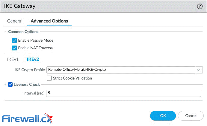 IKE Gateway configuration - Advanced Options - Click to enlarge
IKEv2 Tab
- IKE Crypto Profile: Select a profile. Our example uses the IKE Crypto profile created in the previous step.
- Strict Cookie Validation: When enabled, IKEv2 cookie validation is always enforced. The initiator must send an IKE_SA_INIT containing a cookie.
- Liveness Check: All IKEv2 packets are used as liveness checks. When this option is checked, the firewall will send empty information packets after the peer has been idle for the specified number of seconds (2 – 100).
Step 4 – Configure IPSec Crypto Profile - IKE Phase 2
Next step is to configure the IPSec Crypto profile. This is used to specify the protocols and algorithms for identification, authentication and encryption based on IPSec SA negotiation (IKEv1 Phase 2). Navigate to Network > Network Profiles and then IPSec Crypto. When ready, click on the Add button:
 Creating an IPSec Crypto profile - Click to enlarge
After clicking Add, the IPSec Crypto Profile window will appear, allowing us to configure the profile. The parameters must match with the remote peer for the IKE Phase-2 negotiation to be successful:
 Configuring an IPSec Crypto - Click to enlarge
Below are a few options that require special consideration:
- IPSec Protocol: Used to secure data traversing the VPN tunnel. ESP protocol is recommended as it provides connection confidentiality (encryption) and authentication (AH).
- Encryption: Only available when ESP is selected above. It’s recommended to use AES encryption as DES/3DES are weak and vulnerable algorithms.
- Authentication: SHA256 or stronger is recommended as MD5 and SHA1 are not consider secure.
- DH Group: Diffie-Hellman (DH) group 14 (2048-bit) for IKE. Higher group numbers provide higher security.
- Lifesize: Optionally, select the amount of data that the key can used for before renewing.
At the time of writing, Meraki firmware version MX 18.107.2 supports up to aes-256-cbc IPSec encryption, which is weaker than aes-256-gcm. Regardless this limitation, both are configured on the Palo Alto firewall and aes-256-gcm is set as the preferred encryption (higher on the list) to be used automatically when supported by Meraki.
At the time of writing, Meraki firmware version MX 18.107.2 supports up to IPSec DH Group 14 (Phase 2 – PFS Group setting on Meraki).
Step 5 – Create IPSec Tunnel
This is the final step required to configure the IPSec tunnel between the two endpoints. To being, navigate to Network > IPSec Tunnels, then click on the Add button:

Next, we can configure the IPSec Tunnel parameters as shown below:
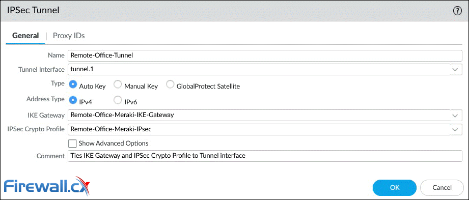
Below are a few options that require special consideration:
- Tunnel Interface: Click and select from the dropdown list interface tunnel.1.
- Type: Contains a number of additional complex settings around IKE, IPSec, Replay protection and more. Leave this to Auto Key.
- Address Type: Select the IP address type IPv4 (default).
- IKE Gateway: Select from the dropdown list, the IKE Gateway profile previously configured.
- IPSec Crypto Profile: Select from the dropdown list the IPSec profile previously configured.
- Tunnel Monitor (Advanced Options): An optional parameter, not used in our setup, that allows the monitoring of tunnel failures and automatic failover to another interface. Requires IP address assigned to the tunnel interface.
When ready, click on OK to save your settings. The dashboard will now show the configured IPSec Tunnel:

The Red dot IKE Info status indicates that IKE Phase-1 SA is not available or has expired. The Red dot Tunnel info status indicates that IPSec Phase-2 SA is not available or has expired.
As soon as the peer VPN gateway (Meraki MX) is configured and the VPN is established, both status indicators will turn green.
The IPSec tunnel configuration is complete at this point, however we still need to configure the VPN traffic routing and security policies to allow VPN traffic through.
Step 6 – Configure VPN Routing (Remote Site Traffic)
This step involves configuring the Palo Alto firewall to route interesting traffic (VPN traffic) through the IPSec tunnel.
Under Network > Virtual Router, click on Static Routes to add a new route to the remote network(s):
")
Be sure to enter the correct remote IP network (172.19.153.0/24) and tunnel interface (tunnel.1). Click OK when done.
Note: While the remote network is a Class C network split into smaller VLAN networks (subnetted), at this point we summarize it with a single entry (172.19.153.0/24).
Below is the configured static entry:

Step 7 – Configure Security Policies (IKE/IPSec & Remote Site Traffic)
The final step involves configuring the necessary security policies to:
- Allow IKE negotiation and IPSec tunnel to be established. See policy 17 below.
- Allow the remote office (172.19.153.0/24) access local resources (192.168.3.0/24) and vice versa. See policies 18-19 below.
- Allow the remote office access the internet (Full Tunnel mode). Note that a NAT policy, for the remote network, will also be required for outbound internet traffic. See policy 20 below.
Pay extra attention to the Source and Destination Zone in policy 17. The VPN tunnel initiates and terminates on the firewall's public (untrusted) interface. Once the tunnel is established, site-to-site user traffic (Policies 18 & 19) flows between zones Remote-Sites-VPN-Zone (Tunnel.1) and Trusted-Zone (internal interface).
 Configuring VPN security policies - Click to enlarge
When building the security policies, we must be mindful that Tunnel.1, assigned to the Remote-Sites-VPN-Zone zone, is the interface to reach the remote site.
The remote site's internet traffic will flow between zones Remote-Sites-VPN-Zone (Tunnel.1) and Untrusted-Zone (public interface).
At this point we've completed the Palo Alto firewall setup and can now continue configuring the Meraki MX security appliance.
Meraki MX VPN Configuration
Thanks to Meraki’s intuitive and simple GUI, configuring the Site-to-Site VPN is simple and painless task. Experienced Cisco engineers with years of CLI experience will appreciate how quickly we can configure a Meraki VPN compated to a Cisco IPSec or ASA Firewalls. Meraki
Step 1 – Enable Site-to-Site VPN
From the Meraki dashboard, select Security & SD-WAN > Configure > Site-to-site VPN:
 Accessing the Site-to-Site VPN section
At the Site-to-site VPN page, click on Hub (Mesh) to enable the VPN configuration section:
 on Meraki MX") Enabling Site-to-site VPN Hub (Mesh)
Enabling Site-to-site VPN Hub (Mesh)
When ready click the Save button at the lower right corner to save your changes.
Step 2 - Enable VPN Mode for Local Networks
Next, scroll down to the VPN Settings section and enable VPN mode for all the local VLAN networks that need to traverse the VPN tunnel:

Step 3 – Configure Non-Meraki VPN Peer
Next, scroll down to Organization-wide settings and click on Add a peer under the Non-Meraki VPN peers subsection:

A new row appears with a number of parameters to be used for the VPN peer configuration:

The row contains a total of 9 fields to be populated. Below are all options/fields:
- Name: Enter a description for the IPSec VPN tunnel.
- IKE Version: This should be identical to that configured on the Palo Alto Firewall IKE Gateway We’ve selected IKEv2.
- IPSec policies: Contains settings for IKE Phase 1 and Phase 2 negotiations. These must match the policies configured on the Palo Alto firewall. This is covered extensively below.
- Public IP/Hostname: Enter the remote VPN Gateway IP or FQDN. Note: FQDN peering requires firmware 18.1 or higher.
- Local ID: Format and identification of the peer VPN gateway used with the pre-shared key for both IKEv1 Phase 1 SA and IKEv2 SA This must match the Peer Identification value used on the Palo Alto IKE Gateway profile (
This email address is being protected from spambots. You need JavaScript enabled to view it. ). If the remote end (Meraki MX) has a dynamic IP, you can use an email address as in our example. When left empty, the Meraki MX will use its Public IP as the Local ID. - Remote ID: Optional field used to identify the remote peer. This is to be configured when the Local ID of the remote peer is anything other than its Public IP.
- Private Subnets: The remote subnets that need to be reachable via this VPN tunnel. Below we show an example of Split Tunnel and Full Tunnel mode.
- Preshared secret: This should be the same key configured in the Palo Alto IKE Gateway
- Availability: Used to define how many MX/Z1 appliances will connect via VPN to this host. Think ‘Mesh VPN topology’. Populated by default with the All networks tag, this settings can be left as is.
Take note that settings in this section apply to all Meraki VPN peers within the organization. This is also mentioned right under the sections's title "Organization-wide settings". If for example there are 2 Meraki MX appliances in your organization dashboard, both of them will be configured with these settings.
Step 4 – Configure IPSec Policies (Phase 1 & Phase 2)
This set involves configuration of IPSec policies, essential for the VPN tunnel to work. To begin, under the Organization-wide settings > Non-Meraki VPN peer, click on the Default text link under IPSec policies column. The pop-up window will present the different configuration options for both Phase 1 and Phase 2. Below are the settings configured to match the Palo Alto configuration:
 Configuring Phase 1 and Phase 2 IPSec Policies
Step 5 - Split Tunnel and Full Tunnel Mode
Depending on your requirements, you can configure the VPN to carry selected traffic (Split Tunnel mode) or all traffic (Full Tunnel mode).
With Split Tunnel, only traffic between the two sites will traverse the VPN tunnel, as shown in the below diagram:

All other traffic (internet traffic) on the remote site will automatically be sent directly to the internet.
For Split Tunnel mode, enter the required networks that need to traverse the VPN, in the Private subnets field, of your Non-Meraki VPN peers section:
 Split Tunnel mode: Adding private subnets to the Meraki VPN tunnel
In Full Tunnel mode, all remote site traffic, including internet traffic, is sent through the VPN tunnel, as shown in the diagram below:

Full Tunnel mode has the added benefit of leveraging the Palo Alto's advanced packet inspection, to protect the remote site. by blocking access to malicious sites, enforcing organization-wide security & internet access policies, leveraging SSL decryption, DNS protection, Wildfire file inspection, and more. While this setup adds additional traffic to the head-end site, it provides superior protection to the remote site.
There are a few areas to consider when implementing Full Tunnel mode:
- The Hub (HQ) internet link(s) utilization are likely to increase as they carry all remote site traffic.
- Remote site internet speed is restricted by the Hub's download/upload speeds.
- IPSec VPN throughput is limited to the endpoints VPN hardware capabilities. Larger models often offer greater IPSec VPN throughput.
To configure Full Tunnel mode on the Meraki MX appliance, enter 0.0.0.0/0 (all networks) in the Private subnets field, of your Non-Meraki VPN peers section:
 Full Tunnel mode: Forcing all traffic through the Meraki VPN tunnel
When using Full Tunnel mode, dont' forget to configure the necessary Security and NAT policies on the headend Palo Alto firewall. These policies are necessary for the remote site to access the internet.
Step 6 - Initiate and Test the VPN Tunnel
This point, the IPSec VPN tunnel between both sites is complete. We are now ready to initiate the VPN tunnel by generating interesting traffic. Remember, VPN tunnels are initiated by the remote site when they are on dynamic internet IPs. When both HQ and remote site are on static IPs, the VPN tunnel can be initiated by either end.
Select Security & SD-WAN > Appliance status, then Tools from the menu. In the Ping section, click on the Source IP Address drop down menu and select VLAN 1, or any other local network that has VPN mode enabled, then enter an IP address. When ready, click the Ping button:
 Generating interesting traffic to bring up the IPSec VPN Tunnel
The IP address can be either a valid remote IP or any internet IP (assuming Full Tunnel mode is configured).
Once the command is executed, a graph will appear showing the ping time response:

The graph is updated roughly every 2 second due to the backend delay between the Meraki MX device, Meraki Cloud and Meraki Dashboard.
Do not be concerned if the first ping packets timeout (as above). This is expected behavior as the tunnel requires a few seconds to be established before packets can traverse it.
Moving back to the Palo Alto firewall, the status column for both Tunnel and IKE are now green, confirming that the VPN tunnel is up:
 Palo Alto Firewall IPSec Tunnels & IKE Status - Click to enlarge
Summary
This article showed how to configure a site-to-site IPSec VPN tunnel between a Palo Alto firewall and Meraki MX security appliance. We explained all steps involved on the Palo Alto firewall including how to create a Tunnel interface, configure IKE Crypto profile, IKE Gateway, IPSec Crypto Profile and IPSec Tunnel. We talked about the recommended IPSec encryption algorithms, configuring VPN routing and special considerations for your Security & NAT Policies. We then explained how to configure the Meraki MX appliance using the Non-Meraki VPN peer and all necessary parameters (IPsec policies, authentication, preshared secret, etc). Finally, we talked about Full tunnel mode, Split tunnel mode and other important considerations for each mode.
Your IP address:
3.135.219.166
All-in-one protection for Microsoft 365

FREE Hyper-V & VMware Backup

Wi-Fi Key Generator
Follow Firewall.cx
Network and Server Monitoring

Recommended Downloads
Cisco Password Crack
Decrypt Cisco Type-7 Passwords on the fly!
Bandwidth Monitor

Free PatchManager

EventLog Analyzer

Firewall Analyzer

Security Podcast