


 Network Switches are the evolution of Hubs and Repeaters, and enable the creation of networks by connecting multiple devices together. They are critical components in computer networking and are used to connect devices like computers, printers, and servers in local area networks (LANs) and wide area networks (WANs). Switches are designed to manage the flow of data between devices, ensuring that each device is able to communicate efficiently and effectively with other devices on the network.
Switches operate at the data link layer (layer 2) of the OSI (Open Systems Interconnection) model and use MAC (Media Access Control) addresses to identify devices on the network. When a device sends data to another device on the network, the switch reads the MAC address of the data packet and determines the best route for the packet to take to reach its destination. This process is called packet switching, and it allows multiple devices on a network to communicate simultaneously without interfering with each other.
There are various types of switches, including unmanaged switches, managed switches, and Layer 3 switches. Unmanaged switches are basic switches that are easy to set up and use, while managed switches offer more advanced features and greater control over the network. Layer 3 switches are used in large networks and are capable of routing data at the network layer of the OSI model. Switches are critical components in modern networks and play an important role in enabling communication and data exchange between devices.
Switches (Layer-2 Switching) do not receive and transmit data throughout every port, like hubs, but instead examine a packet's destination by checking the MAC address. The destination MAC address is always located at the beginning of the packet (see Ethernet II Protocol article) as shown below:
A switch will then forward the frame via the intended port, or out all its ports, depending if it finds an entry for this MAC address in its memory (filter table). This process is explained in more detail later in this article.
Switches use Application Specific Integrated Circuits (ASIC's) to build and maintain filter tables. Layer-2 switches switch packets between ports at a faster rate compared to routers, simply because routers need to examine the Network layer (layer-3) information of the packet, which is higher up in the OSI model and requires additional processing power and time.
- They provide hardware based bridging (MAC addresses)
- They work at wire speed, therefor have low latency
-
They come in 3 different types: Store & Forward, Cut-Through and Fragment Free (Analysed later)
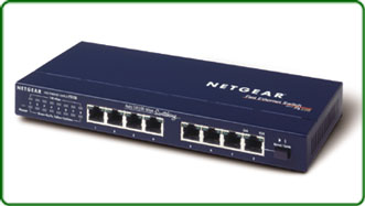
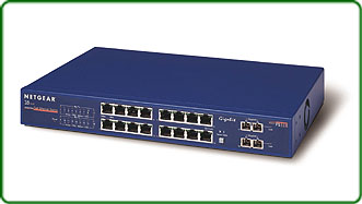
Physically, it's difficult to tell a switch from a hub as they both look alike. The difference between them is under the hood! The photos below show a 8-port hub (left) and 18 port switch (right). Notice the switch provides two ports on the far right - these are uplink ports, allowing the switch to connect to the rest of the network (other switches):
The Three Operating Stages of a Network Switch
Network switches operate in three stages: learning, forwarding, and filtering.
- Stage 1: Learning
- Stage 2: Forwarding
- Stage 3: Filtering
- Loop Avoidance (Optional)
Overall, the three stages of learning, forwarding, and filtering allow the network switch to effectively manage the flow of data on a computer network, ensuring that devices can communicate with each other efficiently and securely.
Stage 1: Address Learning
The address learning phase of a network switch is the process by which the switch builds and maintains a table of MAC addresses and their corresponding switch ports, known as the MAC address table or the Content Addressable Memory (CAM) table. When a switch receives a frame, it examines the source MAC address of the frame and records it in the MAC address table along with the port on which the frame was received. This allows the switch to forward future frames to that device more efficiently, without having to flood the network with unnecessary traffic.
During the address learning phase, the switch also updates its MAC address table as it receives frames with new source addresses. If the switch already has an entry for a particular MAC address, it updates the associated port information. If the switch does not have an entry for the MAC address, it adds a new entry to the table.
It is important to note that the MAC address table has a limited size, usually a few thousand entries (8000-10,000), and can become full if the switch receives frames from too many devices. When the table becomes full, the switch must discard old entries to make room for new ones. This can result in temporary network disruptions as the switch re-learns the addresses of devices that it has not seen in a while.
Overall, the address learning phase is a crucial aspect of switch operation, as it allows switches to efficiently forward frames and reduce network congestion. By maintaining an up-to-date MAC address table, switches can ensure that network traffic is delivered to the correct destination with minimal delay.
The diagrams below shows how frames are forwarded out all switchports when the destination MAC address is unknown (there is no entry in the MAC address table). This is usually the case when a switch is initially powered on (or has an empty MAC address table). In this example, Node 1 sends a packet desitined to Node 2. The switch at this point has already inserted Node1's MAC address in its MAC address table:

And after the first frame has been successfully received by Node 2, it then sends a reply to Node 1. The switch is now aware of the two nodes MAC addresses and will send all frames between them, out through the switchports they are connected to:

Notice how Node 2's frame destined to Node 1, is not transmitted out every switchport . The switch is now aware of the switch ports both Node 1 and Node 2 are connected to:
Forward/Filter Decision
When a frame arrives at a switch, the switch examines the destination MAC address of the frame to determine which port it should forward the frame to. As noted previously, the switch maintains a table, called the MAC address table or the CAM table, which maps MAC addresses to their associated switch ports. If the destination MAC address is already in the MAC address table, the switch will forward the frame out the corresponding port. If the destination MAC address is not in the table, the switch will flood the frame to all ports except the one on which it was received.
This is known as unknown unicast flooding and ensures that the frame reaches its intended destination. Once the frame reaches its destination, the switch updates its MAC address table with the source MAC address and the port on which the frame was received, so that it can forward future frames to that device more efficiently.
Loop Avoidance (Optional) - Spanning-tree protocol
The Spanning Tree Protocol (STP) is a networking protocol designed to prevent loops in networks with redundant links. When multiple paths are available between devices in a network, a loop can occur if the same packet is forwarded indefinitely between devices. This can cause network congestion and ultimately result in a network outage. STP solves this problem by creating a loop-free logical topology for the network.
STP works by selecting a root bridge, which is the device that has the highest priority in the network. Once the root bridge and port roles have been determined, STP builds a tree-like topology that includes all devices in the network. The topology is designed to ensure that there is only one active path between any two devices, which prevents loops from occurring. The tree-like topology is also designed to provide redundancy in the event of a link failure. If a link fails, STP recalculates the topology to find a new path between the affected devices.
STP has several variations, including Rapid Spanning Tree Protocol (RSTP) and Multiple Spanning Tree Protocol (MSTP). RSTP is an improvement on STP that reduces the time it takes for the network to recover from link failures. MSTP is a protocol that allows multiple VLANs to be mapped to a single spanning tree instance, which reduces the number of spanning tree instances required in a network.
In summary, STP is a networking protocol that creates a loop-free logical topology for networks with redundant links. By selecting a root bridge and assigning roles to other devices in the network, STP ensures that there is only one active path between any two devices, which prevents network congestion and outages. STP operates in three phases and has several variations, including RSTP and MSTP.
Switching Modes: Store-and-forward, Cut-through & Fragment-free
There are three primary switching methods: store-and-forward, cut-through, and fragment-free. While all three methods are analyzed in detail, the below diagram shows the portion of a receiving frame a switch will process (check), before forwarding it out its intended port(s):

Store-and-forward switching is the most common method and involves the switch receiving and buffering the entire frame before forwarding it to the destination device. During this process, the switch performs error checking on the frame to ensure it is complete and error-free. If the frame is damaged, the switch discards it. Store-and-forward switching is considered the most reliable switching method as it ensures that only complete, error-free frames are forwarded, but it also has the highest latency due to the buffering and error checking process.
Cut-through switching is a faster method than store-and-forward, as the switch starts forwarding the frame as soon as it reads the destination MAC address. With cut-through, the switch only buffers the minimum amount of the frame (up to the destination MAC address section) required to determine the destination port. Cut-through switching is faster than store-and-forward because it does not wait for the entire frame to be received and verified before forwarding. Keep in mind that this method can forward corrupted frames since there is no error checking before forwarding.
Fragment-free switching is a variation of cut-through switching that reads the first 64 bytes of a frame before forwarding it. This is done to prevent forwarding of frames that may have been damaged during transmission. In general, the first 64 bytes of a frame contain the frame header, which includes the source and destination MAC addresses, as well as the frame type. By reading the first 64 bytes, fragment-free switching can ensure that the frame is not corrupted without having to wait for the entire frame to be received.
Generally speaking, store-and-forward switching is the most reliable but has the highest latency due to the buffering and error checking process. Cut-through switching is faster than store-and-forward but can forward corrupted frames. Fragment-free switching is a variation of cut-through that reads the first 64 bytes of a frame before forwarding it, which reduces the likelihood of forwarding corrupted frames. The choice of switching method depends on the specific needs of the network, and a combination of these methods can be used in larger networks to achieve a balance between reliability and speed.
Network Switches Memory Buffer
The memory buffer in a network switch is an essential component that plays a critical role in ensuring efficient and reliable data transmission. The buffer is responsible for temporarily storing incoming data packets before forwarding them to their destination. Without a memory buffer, the switch would be unable to handle high volumes of network traffic, resulting in packet loss and network congestion. The buffer also helps to prevent data loss by holding packets in case of congestion, allowing time for the switch to clear the congestion and forward the packets. The size of the buffer is an important factor in determining the performance of the switch, as it determines the amount of data that can be temporarily stored. A switch with a larger buffer can handle more traffic and is better equipped to handle bursts of data. As such, the memory buffer is a critical component in ensuring reliable and efficient network performance.
Network Bridges
A network bridge is a device that connects two or more separate network segments and forwards traffic between them. Bridges operate at the data link layer of the OSI model and use the MAC address of devices to determine where to forward traffic. When a bridge receives a frame from one network segment, it examines the destination MAC address of the frame and forwards it to the appropriate segment based on the MAC address table it has learned. The bridge also filters out any frames with destination MAC addresses that are not present on the other side of the bridge, helping to reduce unnecessary network traffic.
Bridges are commonly used to segment networks, isolate network problems, and extend the reach of networks by connecting segments over long distances. With the advent of more advanced network devices such as switches and routers, bridges have become less common but still serve a useful purpose in some network configurations.
Interesting facts:
-
Bridges are software based, while switches are hardware based because they use an ASICs chip to help them make filtering decisions.
-
Bridges can only have one spanning-tree instance per bridge, while switches can have many.
-
Bridges can only have upto 16 ports, while a switch can have hundreds!
Summary
This article explained how network switches operate and compared them with hubs. We examined the three operating stages of a switch: learning, forwarding, and filtering, and provided an overview of network loop avoidance with the help of the Spanning-Tree protocol. We talked about the three switching modes used by switches to forward frames: Store-and-forward, Cut-through & Fragment-free, and how the switch memory buffer plays a critical role in this process. Lastly touched on network bridges and how they we used in the early days to segment networks.
Free eBook - Endpoint Security

Enterprise-Class Cloud & Network Monitoring

Bandwidth Monitor

Wi-Fi Key Generator
Network and Server Monitoring

Follow Firewall.cx
Recommended Downloads
Cisco Password Crack
Decrypt Cisco Type-7 Passwords on the fly!
Automated Patching Solution

Firewall Analyzer


