 While the VLAN Tagging article briefly covered the IEEE 802.1q protocol this article will continue building upon it by further analyzing the IEEE 802.1q Trunk Link Protocol. The IEEE 802.1q tagging method is the most popular as it allows the seemless integration of VLAN capable devices from all vendors supporting the protocol.
IEEE 802.1q Analysis
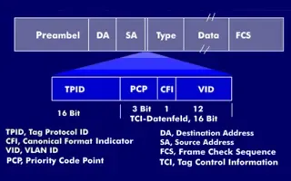
The IEEE 802.1q tagging mechanism seems quite simple and efficient thanks to its 4-byte overhead squeezed between the Source Address and Type/Length field of our Ethernet II frame:
The process of inserting the 802.1q tag into an Ethernet II frame results in the original Frame Check Sequence (FCS) field to become invalid since we are altering the frame, hence it is essential that a new FCS is recalculated, based on the new frame now containing the IEEE 802.1q field. This process is automatically performed by the switch, right before it sends the frame through a trunk link. Our focus here will be the pink 3D block, labeled as the IEEE 802.1q header.
The IEEE 802.1q Header
As noted, the 802.1q header is only 4 bytes or 32 bits in length while within this space there is all the necessary information required to successfully identify the frame's VLAN and ensure it arrived to the correct destination. The diagram below analyses all fields contained in a 802.1q header:
The structure is quite simple as there are only 4 fields when compared with the 11 fields InterSwitch Link (ISL) has. We will continue by analysing each of these fields in order to discover what the protocol is all about.
TPID - Tag Protocol IDentifier
The TPID field is 16 bit long with a value of 0x8100. It is used to identify the frame as an IEEE 802.1q tagged frame.
Note: The next three fields, Priority, CFI and VLAN ID are also known as the TCI (Tag Control Information) field and are often represented as one single field (TCI Field).
Priority
The Priority field is only 3 bits long but used for prioritisation of the data this frame is carrying.
Data Prioritisation is a whole study in itself but we won't be analysing it here since it's well beyond the scope of our topic. However, for those interested, data prioritisation allows us to give special priority to time-latency sensitive services, such as Voice Over IP (VoIP), over normal data. This means that the specified bandwidth is allocated for these critical services to pass them through the link without any delay.
The IEEE 802.1p priority protocol was developed to provide such services and is utilised by the IEEE 802.1q tagging protocol.
The Priority field is approximately 3 bits long, allowing a total of 2^3=8 different priorities for each frame, that is, level zero (0) to seven (7) inclusive.
CFI - Canonical Format Indicator
The CFI field is only 1 bit long. If set to 1, then it means the MAC Address is in non-canonical format, otherwise 0 means it is canonical format. For Ethernet switches, this field is always set to zero (0). The CFI field is mainly used for compatibility reasons between Ethernet and Token Ring networks.
In the case where a frame arrives to an Ethernet port and the CFI flag is set to one (1), then that frame should not be forwarded as it was received to any untagged port (Access Link port).
VLAN ID - Virtual Local Area Network Identifier
The VLAN ID field is perhaps the most important field out of all because we are able to identify which VLAN the frame belongs to, allowing the receiving switch to decide which ports the frame is allowed to exit depending on the switch configuration.
For those who recall our VLAN Tagging article, we mentioned that the IEEE 802.1q tagging method supports up to 4096 different VLANs. This number derives from the 12 bit VLAN ID field we are analysing right now and here are the calculations to prove this: 2^12=4096, which translates from VLAN 0 to VLAN 4095 inclusive.
Summary
That completes our analysis on the IEEE 802.1q protocol. As a last note, you should remember that this protocol is the most wide spread tagging method used around the world that supports up to 4096 VLANs!
Enterprise-Class Cloud & Network Monitoring

Bandwidth Monitor

Wi-Fi Key Generator
Network and Server Monitoring

Follow Firewall.cx
Recommended Downloads
Cisco Password Crack
Decrypt Cisco Type-7 Passwords on the fly!
Automated Patching Solution

Firewall Analyzer