


The device driver software receives a frame of IP, IPX, NetBIOS, or other higher-layer protocol data. From this data, the device driver constructs a frame, with appropriate Ethernet header information and a frame check sequence at the end.
The circuitry on the adapter card then takes the frame and converts it into an electrical signal. The voltage transitions in the transmitted bit stream are in accordance to the format called Manchester Signal Encoding. Manchester encoding describes how a binary ONE and ZERO are to be represented electrically. Manchester encoding is used in all 10 Megabit per second Ethernets; for example, 10BASE2 Thin Ethernet, 10BASE5 Thick Ethernet and 10BASE-T Twisted-Pair Ethernet.
Here we see an example of the signal transitions used to encode the hexadecimal value "0E", which converts to "00001110" in binary:
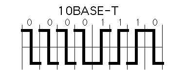
Notice that there is a consistent transition in the middle of each bit-time. Sometimes this transition is from low-to-high and sometimes it's from high-to-low. This is the clock transition. The receiving adapter circuitry 'locks on' to this constant signal transition and, thereby, identifies the timing to determine the beginning and end of each bit.
To represent a binary ONE, the first half of the bit-time is a low voltage; the second half of a bit is always the opposite of the first half, that's how the clock transition is created. To represent a binary ZERO, the first half of the bit-time is a high voltage. You see that sometimes there is an additional transition at the beginning of a bit-time (not drawn in in the diagram above) where the signal is pulled either up or down in preparation for the next bit.
Consider what happens if an external electromagnetic field interferes with the Manchester bit encoding. This external field could be the result of an electric motor, radio transmission or other source of interference. You should be able to see that if the Manchester signal is disrupted the bits will be destroyed - because the clock signal will be disrupted.
It would not be reasonably possible for electrical interference to change a binary ONE into a binary ZERO. Since each bit is symmetrical (second half is always opposite the first half) the result of electrical noise would be the destruction of the bit, not a change in bit value.
Enterprise-Class Cloud & Network Monitoring

Bandwidth Monitor

Wi-Fi Key Generator
Network and Server Monitoring

Follow Firewall.cx
Recommended Downloads
Cisco Password Crack
Decrypt Cisco Type-7 Passwords on the fly!
Automated Patching Solution

Firewall Analyzer
