

Latest Articles
Boost Your Microsoft 365 Security with Expert Guidance and Proven Best Practices
 This article serves as a comprehensive guide to fortifying the security posture of Microsoft 365, covering essential aspects ranging from foundational security principles to advanced strategies for optimizing productivity without compromising security. From introducing the fundamental Microsoft 365 Security Essentials to defining proactive measures such as regular audits, secure configurations, and Data Loss Prevention (DLP) protocols, this guide equips organizations with the knowledge necessary to establish a resilient security framework.
Furthermore, the article delves into protecting user identities and sensitive data, proven strategies such as Multi-Factor Authentication (MFA), identity protection mechanisms, and data encryption techniques. By prioritizing these measures, businesses can mitigate the risk of unauthorized access and data breaches, thereby bolstering trust and compliance with regulatory standards.
Moreover, the article explores how organizations can optimize security measures to enhance productivity, emphasizing the role of role-based access control (RBAC), security awareness training, and the utilization of security dashboards and reports. By integrating security seamlessly into daily workflows, businesses can foster a culture of vigilance while empowering employees to navigate digital environments securely.
Key Topics:
- Introduction to Microsoft 365 Security Essentials
- How to Implement Proactive Security Measures
- Protecting User Identities and Data
- Learn More About Safeguarding Against Common Threats
- Optimizing Security for Enhanced Productivity
- Summary
Introduction to Microsoft 365 Security Essentials
Challenges & Solutions to Managing Firewall Rules in Complex Network Environments
 In today's interconnected digital landscape, where businesses rely heavily on networked systems and the internet for their operations, the importance of cybersecurity cannot be overstated. Among the essential tools in a cybersecurity arsenal, firewalls stand as a frontline defense against cyber threats and malicious actors.
One of the primary functions of a firewall is to filter traffic, which entails scrutinizing packets of data to determine whether they meet the criteria set by the organization's security policies. This process involves examining various attributes of the data packets, such as source and destination IP addresses, port numbers, and protocols. By enforcing these rules, firewalls can thwart a wide range of cyber threats, including unauthorized access attempts, malware infections, denial-of-service attacks and more.
Enforcing and managing firewall rules effectively can be a daunting task, particularly in complex network environments with numerous rules, policies and configurations. While solutions like ManageEngine Firewall Analyzer step in, to offer a comprehensive way to streamline firewall rule management and enhance security posture, it’s worthwhile take a look at the real challenges firewall rule management present across all known platforms such as Cisco (FTD, Firepower, ASA), Palo AltoPalo Alto Next-Gen firewalls, Checkpoint, Fortinet, Juniper and more.
Key Topics:
- Challenges in Firewall Rule Management
- How to Simplify Firewall Rules
- The Benefits of Effective Firewall Rule Management
- Summary
Challenges with Firewall Rule Management
Configuring QoS on Palo Alto Firewalls: Class-based Policies, QoS Profiles, Enabling QoS on Firewall Interfaces
 This article’s purpose is to help you quickly master Palo Alto QoS concepts and learn to configure QoS on Palo Alto Firewalls in a simple and efficient way. QoS is considered a complicated topic however thanks to Palo Alto’s intuitive firewall GUI interface and our real-scenarios, you’ll quickly grasp all necessary QoS basics and be ready to implement your own QoS policies!
You’ll learn basic QoS terms such as Ingress and Egress traffic, Differentiated Service Code Point (DSCP), Traffic Policing, Traffic Shaping, Palo Alto QoS Classes, Palo Alto QoS Policies, how to build Palo Alto QoS policies, how to configure Palo Alto QoS Classes and finally how to enable and monitor QoS on Palo Alto firewall interfaces (both standalone & AE Aggregate interfaces), view QoS bandwidth graphs and more!
Key Topics:
- Introduction to Palo Alto QoS
- Palo Alto QoS Classes
- Palo Alto QoS Policies
- Configuring QoS Class-based Policies & Profiles
- Enabling QoS on Palo Alto Firewall Physical & Aggregate (AE) Interfaces
- Summary
Find more great articles by visiting our Palo Alto Firewall Section.
Introduction to Palo Alto QoS
QoS was born from the IEEE group during 1995-1998 by establishing the standard IEEE 802.1P. The main purpose of QoS is to prioritise desired traffic over other type of traffic or to limit the amount of bandwidth applications can consume, by utilizing different mechanisms. This ensures network performance, avoids bottlenecks, congestion or overutilization of network links. A frequently used example of QoS is the prioritising Real-time traffic e.g voice or video, over other type of traffic:
 QoS Priority Queues - Packet classification and prioritization
In the example above, voice packets (blue) are given a higher priority against others, therefore immediately being forwarded by the firewall out via the output interface. Since voice packets are very sensitive to delay, they are usually handled with priority to avoid issues in a real-time voice streams e.g VoIP telephone call between two endpoints.
Overview of QoS Configuration on Palo Alto Firewalls
Dealing with Security Audit Challenges: Discovering vulnerabilities, unauthorized access, optimize network security & reporting
 The utilization of log analyzers, such as Firewall Analyzer, in network infrastructure plays a pivotal role in enhancing cybersecurity and fortifying the overall security posture of an organization. Security audits, facilitated by log analyzers, serve as a critical mechanism for systematically reviewing and analyzing recorded events within the network.
This proactive approach enables the identification of potential security risks, unauthorized access attempts, and abnormal activities that might signify a breach. The log analyzer sifts through vast amounts of data & logs, providing insights into patterns and anomalies that might go unnoticed otherwise.
By uncovering vulnerabilities and irregularities, organizations can take timely corrective actions, preventing potential security breaches. Moreover, the information gleaned from these audits is instrumental in formulating a comprehensive security strategy that extends across the entire network infrastructure.

This strategic approach ensures a holistic defense against cyber threats, fostering a resilient and adaptive cybersecurity framework that aligns with the evolving landscape of security challenges.
This article will delve into the concept of security audits and how a product like Firewall Analyzer can streamline this crucial procedure.
Key Topics:
- Security Audits Explained
- Security Audit Challenges
- Tool for Effective Network Security Management
- Conducting a Security Audit with Firewall Analyzer
- Summary
Download your copy of ManageEngine's popular Firewall Analyzer here.
Security Audits Explained
Your IP address:
3.133.160.156
All-in-one protection for Microsoft 365

FREE Hyper-V & VMware Backup

Wi-Fi Key Generator
Follow Firewall.cx
Network and Server Monitoring

Recommended Downloads
Cisco Password Crack
Decrypt Cisco Type-7 Passwords on the fly!
Bandwidth Monitor

Free PatchManager

EventLog Analyzer

Firewall Analyzer

Security Podcast

Featured Categories:


Top Picks:
Differences Between VMware vSphere, vCenter, ES...
World Backup Day with Free Amazon Voucher and P...
Palo Alto Networks Firewall - Web & CLI Initial...

Dealing with Security Audit Challenges: Discove...

VTP Protocol - In-Depth Analysis

Static VLANs
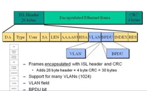
VLAN InterSwitch Link (ISL) Protocol Analysis

InterVLAN Routing - Routing between VLAN Networks

OSPF - Part 3: OSPF Adjacency & Neighbor Forming Process. OSPF Hello Messages, OSPF Database Updates via Link State Requests (LSR & LSU)

Routed Protocols

OSPF - Part 6: OSPF LSA Types - Purpose and Function of Every OSPF LSA