


Configuration of ISDN interfaces on Cisco routers are usually considered a straight-forward process, however there are some details which can cause your ISDN dialer interface to fail.
This article will take you through the basic steps of configuring a Cisco Router to work with ISDN. Below is a table of ISDN Switch Types. Before you attempt to configure ISDN you need to ensure that you know which type of ISDN switch you are connecting to at the Telco.
|
Telco Switch Type |
Cisco Keyword |
|
AT&T Basic Rate Switch |
basic-5ess |
|
Nortel DMS-100 Basic Rate Switch |
basic-dms100 |
|
National ISDN-1 switch |
basic-ni1 |
|
PINX (PBS) Switches with QSIG Signalling per Q.931 |
basic-qsig |
|
NET3 Switch Type for UK , Europe , Asia & Australia |
basic-net3 |
|
AT&T 4ESS (ISDN PRI Only) |
primary-4ess |
|
AT&T 5ESS (ISDN PRI Only) |
primary-5ess |
|
Nortel DMS-100 (ISDN PRI Only) |
primary-dms100 |
|
National ISDN Switch Type |
primary-ni |
|
NTT ISDN PRI Switches ( Japan ) |
primary-ntt |
|
European and Australian ISDN PRI Switches |
primary-net5 |
|
QSIG Signaling per Q.931 |
primary-qsig |
|
No Switch Type |
none |
For a very basic BRI ISDN configuration on a Cisco Router, you need to perform the following steps (that's providing you are not using DDR - Demand Dial Routing);
- Configure the Switch Type (Using switch-type)
- Configure the ISDN Dialer Map; this basically maps the IP Address of the end router's IP Address with its telephone number (Using dialer-map)
- Configure your ISDN Interface IP Address (using interface & ip address)
- Configure a routing rule (using ip route)
For Example,
Router(config)# isdn dialer map ip 10.10.10.2 name main_office 66552
Router(config)# ip route 192.168.0.0 255.255.255.0 10.10.10.2
Router(config)# interface BRI 0
Router(config-if)# ip address 10.10.10.1 255.255.255.0
N.B. If using the DMS-100 and National-1 switch types (as well as AT&T 5ESS), you will need to obtain from you telco the Service Profile Identifier (SPIDs) of which you require one per each Bearer Channel. For these switch types, these need to be configured using the isdn spid1 and isdn spid2 commands. The SPIDs are used to authenticate call requests at the telco's switch. The format for using the SPIDs is isdn spid1 spid-number ldn and isdn spid2 spid-number ldn.
Demand Dial Routing
Since ISDN is a circuit switched technology, you usually pay for the amount of time that the line is active. For this reason, you generally do not want to raise the ISDN line for just any type of traffic. In order to accommodate this, you can configure what's called Demand Dial Routing or, DDR for short. The idea behind DDR is that you to specify the ‘interesting traffic' that will be able to raise the ISDN line.
For example, you can set as ‘interesting traffic', all packets destined towards a specific remote network you connect to. If none of the routed traffic that is heading for that network (on the other side of the ISDN line), the line doesn't get raised. This saves on unnecessary costs due to none essential traffic raising the line.
The way you specify ‘interesting traffic' is with the use of Access Control Lists (ACL's). If the traffic destined for the remote network doesn't match this interesting traffic, then the line stays down, otherwise the line is raised and traffic is allowed to travel to the remote network. It's worth mentioning here that although you have defined this “Interesting” traffic, it doesn't mean that other traffic will not be allowed to travel along the ISDN link. If the link is active, any traffic (unless blocked by Access Lists) is allowed to travel the link, therefore keep in mind that the “Interesting” traffic is used only to bring the line up.
You can then create a 2 nd set of ACL's which defining the traffic that can traverse the ISDN line. Also, the DDR works using a counter, like a time-out counter, once the counter reaches a preset configurable threshold, the line will drop again. This threshold is reduced each time “Interesting” traffic is sent over the ISDN Link, therefore it's also only the “Interesting” traffic that is used to maintain the link.
Steps in configuring DDR (assumes part of the basic steps above have already been configured)
- Define Interesting Traffic (Using dialer-list & access-list)
- Assign Interesting Traffic to an Interface (Using dialer-group)
- Define the destination IP address, hostname and telephone number to dial (Using dialer map)
- Define any additional options (Using dialer idle-timeout, dialer fast-idle, dialer load-threshold)
The Additional Options
|
Command |
Description |
| dialer idle-timeout seconds |
Specifies the number of idle time in seconds before the link is dropped. |
| dialer fast-idle seconds |
Specifies the time that a line showing contention can remain idle for before it is dropped in order to allow the other call to be placed. |
| dialer load-threshold load [outbound | inbound |either] |
Specifies the amount of load on the ISDN before the dialer initiates another call to the same destination (i.e. brings up the second channel making the link 128Kbps). The load is a number from 1 to 255, with 255 equalling 100% load. The final parameters specify which direction of traffic to calculate the load from. |
For Example:
Router(config)# access-list 101 permit tcp any any eq http
Router(config)# dialer-list 1 protocol ip list 101
Router(config)# interface BRI 0
Router(config-if)# dialer-group 1
What this example does, is allowing all web traffic (http) from anywhere to anywhere. As you can see, the dialer-list is specifying the 101 access list to dialer-list 1. The dialer-group is then specifying the 1, which links to the dialer-list 1.
Dialer Profiles
On Cisco's website it states that “Dialer Profiles implementation of DRR is based on a separation between the logical and physical interface configurations. Dialer profiles also allow the logical and physical configurations to be bound together dynamically on a per-call basis.”
There are several advantages of Dialer Profiles over Legacy DDR, it is much more scalable then Legacy DDR because Legacy DDR is based on a static binding between the per-destination call and the physical interface configuration. Dialer profiles are point-to-point interfaces which mean we no longer need the layer 3 to layer 2 mapping (layer 2 meaning the telephone number) since the profile can only dial a single location (hence point-to-point).
Since the logical and physical configurations are dynamic, it allows physical interfaces to take on different characteristics based on the logical call requirements that is utilising the physical interface. The final advantage that we will include here is that it enables you to have a backup interface that isn't tying up one of the physical interfaces. Providing a spare interface is available, the backup can be used when it's required.
Dialer Profiles are made up of a Dialer Interface, dialer pool and physical interface. Optionally, you can also have a map class. These are highlighted in the table below
| Dialer Interface | This is the logical call requirements to the point-to-point connection. The following parameters can be configured; the IP address of the destination network (ip address address mask), Layer 2 encapsulation type for example ppp (encapsulation ppp), PPP authentication (ppp authentication chap & pap), the remote routers authentication name (dialer remote-name username), the remote destination to call (dialer string dial-string), dialer pool mapping to use for calls to this destination (dialer pool number), assign dialer interface to a dialer group (dialer group number).
There are other optional parameters such as PPP Mulitlink, idle timeout and more. |
Dialer Pool |
|
| Physical Interface | Here we assign a physical interface into a dialer pool (dialer pool-member number) and assign any additional physical features, such as layer 2 encapsulation (encapsulation ppp), ppp authentication (authentication chap), etc.. |
| Map Class (Optional) |
|
Steps in creating a Dialer Profile (assumes part of the basic steps above have already been configured, such as ISDN type);
- Define a Dialer Interface
- Configure a Dialer String
- Assign Physical Interface to a Dialer Pool, plus any additional Physical attributes
Other steps from the previous sections may need to be performed, for example; if you wanted to active the link using interesting traffic, DDR needs to be configured.
For Example:
Define Dialer Interface
Router(config-if)# ip address 10.10.10.1 255.255.255.0
Router(config-if)# encapsulation ppp
Router(config-if)# ppp authentication chap
Router(config-if)# dialer remote-name remoteoffice
Router(config-if)# dialer string 999666
Router(config-if)# dialer pool 1
Router(config-if)# dialer-group 1
Router(config-if)# exit
Configure Physical Interface:
Router(config-if)# encapsulation ppp
Router(config-if)# dialer pool-member 1
Router(config-if)# ppp authentication chap
Router(config-if)# exit
Configure DDR to specify “Interesting” traffic (http) used to bring the line up:
Router(config)# dialer-list 1 protocol ip list 101
A Simple Example
The following example includes a variety of different items discussed in this document, in order to help you see how they are applied in a real-case scenario. As always, depending on the security policies and network complexity, the configuration can change quite a bit. For simplicity reasons, we've keep the complexity to a minimum.
Our scenario is based upon two routers who occasionally require to connect their networks via an ISDN dial line, in order to transfer data between them.
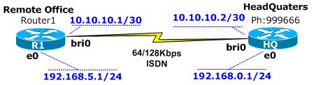
Router 1 – Remote Office
Assign the switch type that we are connecting through to on the physical layer, AT&T Basic Rate Switch telco switch:
Router1(config)# isdn switch-type basic-5ess
Router1(config-if)# ip address 10.10.10.1 255.255.255.252
Configure the encapsulation used when we are connecting through this virtual interface:
Router1(config-if)# encapsulation ppp
Set our ppp authentication to use chap, pap. The ‘Callin' parameter ensures our router authenticates the remote router (HQ) on an incoming call. Since we are always the calling party, it does not expect the remote (HQ) router to authenticate, making this authentication process a one-way direction. Remote Office authenticates to the HQ router:
Router1(config-if)#ppp authentication chap pap callin
Set the username & password for chap/pap authentication protocol & number to dial:
Assign this virtual interface to use any physical interface that's assigned to pool number 1:
The following command is used to define the interesting traffic that can be used to raise this virtual interface. The next command is paired with the "dialer-list 1" command later on. Next, disconnect this call after 300 seconds of inactivity:
Router1(config-if)# dialer idle-timeout 300
Make this link ‘ppp multilink' capable, allowing the aggregation of the two available 64K ISDN lines to a total of 128Kbps and when the incoming or outgoing (either) traffic reaches half of the available bandwidth (125), then bring up the 2 nd ISDN channel:
The commands below takes us into the interface sub command of the physical interface bri0/0, ready for configuring the physical characteristics. Configure the encapsulation for this physical interface. Optional command since we've already included it in the Dialer Interface:
Access lists are used to define interesting traffic. This line specifies that tcp port 80 traffic from anywhere to anywhere is interesting. The second command Maps the access-list with the dialer-group. As you can see, number 1 is used in the dialer-list and dialer-group statements:
Next command creates a route to the 192.168.0.0/24 subnet to go through 10.10.10.2 (will use Dialer1 to get there since it's on the 10.10.10.0 subnet):
Router1(config)# ip route 192.168.0.0 255.255.255.0 10.10.10.2
Router 2 – HeadQuaters
The configuration for the HQ node is similar:
Assign the username & password the remote office router will user while authenticating to this route:
HQ(config)# username remote-office password cisco
HQ(config)# interface dialer1
HQ(config)# description Incoming From Remote-Office
HQ(config-if)# ip address 10.10.10.2 255.255.255.252
HQ(config-if)# encapsulation ppp
HQ(config-if)# ppp authentication chap pap callin
HQ(config-if)# dialer pool 1
HQ(config-if)# ppp multilink
HQ(config-if)# exit
HQ(config)# interface bri0
HQ(config-if)# encapsulation ppp
HQ(config-if)# dialer pool-member 1
HQ(config-if)# exit
HQ(config)# ip route 192.168.5.0 255.255.255.0 10.10.10.1
Summary
Here's the complete configuration without comments:
Router 1 - Remote Office
Router1(config)# interface dialer1
Router1(config)# description Outgoing To HQ
Router1(config-if)# ip address 10.10.10.1 255.255.255.252
Router1(config-if)# encapsulation ppp
Router1(config-if)# ppp authentication chap pap callin
Router1(config-if)# ppp chap hostname remote-office
Router1(config-if)# ppp chap password cisco
Router1(config-if)# ppp pap sent-username remote-office password cisco
Router1(config-if)# dialer string 999666
Router1(config-if)# dialer pool 1
Router1(config-if)# dialer-group 1
Router1(config-if)# dialer idle-timeout 300
Router1(config-if)# ppp multilink
Router1(config-if)# dialer load-threshold 125 either
Router1(config-if)# exit
Router1(config)# interface bri0
Router1(config-if)# encapsulation ppp
Router1(config-if)# dialer pool-member 1
Router1(config-if)# ppp authentication chap
Router1(config-if)# exit
Router1(config)# access-list 101 permit tcp any any eq http
Router1(config)# dialer-list 1 protocol ip list 101
Router1(config)# ip route 192.168.0.0 255.255.255.0 10.10.10.2
Router 2 - Headquaters
HQ(config)# isdn switch-type basic-5ess
HQ(config)# interface dialer1
HQ(config)# description Incoming From Remote-Office
HQ(config-if)# ip address 10.10.10.2 255.255.255.252
HQ(config-if)# encapsulation ppp
HQ(config-if)# ppp authentication chap pap callin
HQ(config-if)# dialer pool 1
HQ(config-if)# ppp multilink
HQ(config-if)# exit
HQ(config)# interface bri0
HQ(config-if)# encapsulation ppp
HQ(config-if)# dialer pool-member 1
HQ(config-if)# exit
HQ(config)# ip route 192.168.5.0 255.255.255.0 10.10.10.1
Free eBook - Endpoint Security

Enterprise-Class Cloud & Network Monitoring

Bandwidth Monitor

Wi-Fi Key Generator
Network and Server Monitoring

Follow Firewall.cx
Recommended Downloads
Cisco Password Crack
Decrypt Cisco Type-7 Passwords on the fly!
Automated Patching Solution

Firewall Analyzer
