


 This article covers the commonly known Unshielded Twisted Pair (UTP) cable and shows how many pairs the UTP Cat5, Cat5e, Cat6 & Cat7 cables consists of, the colour coding they follow, the different wiring standard that exist (T-568A & T-568B) plus the pin number designations for both standards.
We will be mainly focussing on the wiring of CAT5e & 6 cables as they are the most popluar cables around! We'll also cover wiring classic CAT1 phone cables. It is very important to understand UTP cabling standards and how to correctly terminate them.
Cabling is the foundation for a solid network, and implementing it correctly the first time will help avoid hours of frustration and troubleshooting. On the other hand, if you are dealing with a poorly cabled network, this knowledge will help you to find the problem and fix it more efficiently.
Wiring the UTP cables
We are now going to look at how UTP cables are wired. There are two popular wiring schemes that most people use today: the T-568A and T-568B. These differ only in which color-coded pairs are connected -- pairs 2 and 3 are reversed. Both work equally well, as long as you don't mix them. If you always use only one version, you're okay, but if you mix A and B in a cable run, you will get crossed pairs.
UTP cables are terminated with standard connectors, jacks and punchdowns. The jack/plug is often referred to as a "RJ-45," but that is really a telephone company designation for the "modular eight-pin connector" terminated with the USOC pinout used for telephones. The male connector on the end of a patch cord is called a "plug" and the receptacle on the wall outlet is a "jack."

Figure 1. A RG-45 Jack and RJ-45 Plug / Connector
As already mentioned, UTP has four twisted pairs of wires. The illustration shows the pairs and the color codes they have. As you can see, the four pairs are labeled:
Figure 2. Colour codes & Pairs of UTP CAT 5, CAT 5e, CAT6, CAT7 Cable
Pairs 2 and 3 are used for normal 10/100 Mbps networks, while pairs 1 and 4 are reserved. In Gigabit Ethernet, all four pairs are used.
The picture below shows the end of a CAT5e cable with an RJ-45 connector, commonly used to connect computers to a switch. It also shows a stripped CAT5e cable and identifies the four twisted pairs:
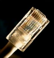

Figure 3. UTP CAT5e cable and stripped twisted pairs
UTP cables are now available in a variety of colours, making it possible to have different coloured cables for different applications.
Figure 4. Different coloured UTP cables
T-568A & T-568B 4-pair Wiring
Ethernet is generally carried in eight conductor cables with eight-pin modular plugs and jacks. The connector standard is called "RJ-45" and is just like a standard RJ-11 modular telephone connector, except it is a bit wider to carry more pins.
Note: Keep in mind that the wiring schemes we are going to talk about are all for straight-through cables only.
The eight-conductor data cable contains four pairs of wires. Each pair consists of a solid colored wire and a white wire with a stripe of the same color. The pairs are twisted together. To maintain reliability on Ethernet, you should not untwist them any more than necessary (about 1 cm). The pairs designated for 10 and 100 Mbps Ethernet are orange and green. The other two pairs, brown and blue are used when Gigabit Ethernet is supported or can be used for a second 10/100 Ethernet line or for phone connections. It should be noted that running a second Ethernet or phone line over an existing UTP cable, is not recommended as UTP wasn’t designed for such applications.
There are two wiring standards for UTP cables, called "T568A" (also called "EIA") and "T568B" (also called "AT&T" and "258A"). The only difference between the two standards is the wiring of two out of four pairs, which are swapped, as shown below.
T-568A is supposed to be the standard for new installations, while T-568B is an acceptable alternative. However, most off-the-shelf data equipment and cables seem to be wired to the T568B specification. T568B is also the AT&T standard. It’s perfectly right to use either wiring standard, however special consideration should be taken so that the same standard is used throughout the whole cabling infrastructure. For existing installations, its best to first check which of the two standards is being used and continue with that standard.
Pin Number Designations for T568B
Note that the odd pin numbers are always the white with stripe color (1,3,5,7). The wires connect to RJ-45 8-pin connectors as shown below:

Figure 5. RJ-45 Connector and Jack with EIA/TIA 568B pinouts
The following table provides the color codes, pair numbers and their function, for the T568B wiring specification:

Figure 6. T568B Pinout configuration, colour code, pairs and their functionality
The wall jack may be wired in a different sequence because the wires are often crossed inside the jack. The jack should either come with a wiring diagram or at least designate pin numbers.
Note that the blue pair is on the center pins; this pair translates to the red/green pair for ordinary telephone lines which are also in the centre pair of an RJ-11 (green=white/blue, red=blue).
Pin Number Designations for T568A
The T568A specification reverses the orange and green connections so that pairs 1 and 2 are on the center four pins, which makes it more compatible with the telephone company voice connections. (Note that in the RJ-11 plug at the top, pairs 1 and 2 are on the center four pins.) The illustrations show the order of colors in T568A:
 Figure 7. RJ-45 Connector and Jack with EIA/TIA 568A pinouts
The following table provides the color codes, pair numbers and their function, for the T568A wiring specification:

Figure 8. T568A Pinout configuration, colour code, pairs and their functionality
The diagram below shows the 568A and 568B in comparison:

Figure 9. Comparing T568A and T568B wiring schemes and pinouts. Front side of the RJ-45 connectors are shown
Where are they used?
The most common application for a straight-through cable is a connection between a PC and a hub or switch. In this case, the PC is connected directly to the hub or switch, which will automatically cross over the cable internally, using special circuits. In the case of a CAT1 cable, which is usually found in telephone lines, only two wires are used. These do not require any special cross over since the phones connect directly to the phone socket.

Figure 10. Straight-thru UTP CAT5/CAT5e cable pinouts
The picture above shows a standard CAT5e straight-through cable used to connect a PC to a hub or switch. You might expect the TX+ of one side to connect to the TX+ of the other side, but this is not the case. When you connect a PC to a hub, the hub will automatically x-over the cable by using its internal circuits. The result is that pin 1 from the PC (which is TX+) connects to pin 1 of the hub (which connects to RX+).This happens for the rest of the pinouts as well.
If the hub didn't cross-over the pinouts using its internal circuits (this happens when you use the uplink port on the hub), then pin 1 from the PC (which is TX+) would connect to pin 1 of the hub (which would be TX+ in this case). So, no matter what we do with the hub port (uplink or normal), the signals assigned to the eight pins on the PC side of things will always remain the same. The hub's pinouts, however, will change depending whether the port is set to normal or uplink.
This article covered UTP Straigh-thru cable pinouts and wiring schemes for both T568A and T568B standards. We examined the UTP cable pairs along with their colour codes along with the RJ-45 connectors and jack.
Next - CAT5 UTP Cross-Over Cable or Back to Network Cabling Section
Free eBook - Endpoint Security

Enterprise-Class Cloud & Network Monitoring

Bandwidth Monitor

Wi-Fi Key Generator
Network and Server Monitoring

Follow Firewall.cx
Recommended Downloads
Cisco Password Crack
Decrypt Cisco Type-7 Passwords on the fly!
Automated Patching Solution

Firewall Analyzer
